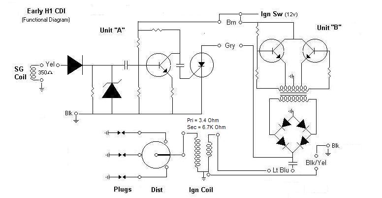
Early CDI Test Procedure by Dayle Edwards (Starfire)
Here is a checklist to test the Early H1 CDI units A and B. If anything is
unclear, please get back to me.
UNIT A
Remove unit A and the battery from the bike. On the bench, crocodile clip leads
are great for this, connect as follows:
1 Connect the unit A BROWN lead to the battery + (positive)
2 Connect the case/housing of unit A to the battery - (negative). ( If there is
a BLACK wire, this is connected to Battery - (negative) also.
3 Connect the GREY wire to one terminal of a low wattage 12 volt test bulb....
an old blinker unit or tailight unit will be fine.
4 Connect the other test bulb terminal to battery + (positive)
5 Touch the YELLOW wire on unit A to the GREY wire unit A
The light bulb should now light up, and continue to stay on when the yellow wire
is disconnected.
6 Disconnect one lead of the test light, and reconnect it again.
The light should remain off, and once again come on when the YELLOW wire is
touched to the GREY wire, unit B.
If the unit A behaves as above, it is probably 99 percent ok. This test does not
voltage test the SCR, but checks its basic operation, if the test light is
always on, the SCR is shorted, Unit A is toast. If the light does not come on,
the SCR is open and/or the trigger amplifier is stuffed, unit A is buggered.
TRIGGER COIL (SG Coil)
If unit A passes the above tests, then:
Remove also the trigger coil from the bike. This is connected to the Unit A as
follows:
1 One wire from the trigger coil is connected to the battery - (negative)
2 The other wire connects to the YELLOW wire of the unit A
3 Now, wave a magnet across the poles of the trigger coil. A suitable magnet can
be obtained from the neighbours loud annoying stereo speakers, the ones that
keep you awake at night.
4 The test light should now come on, and stay on.
If this happens, the trigger coil is OK.
If it doesn't, the trigger coil is faulty.
UNIT B
1 Disconnect unit A from unit B
2 disconnect the ignition coil wires to Unit B
3 Turn on ignition.
4 The Unit should buzz.
5 If no buzz, Unit B is faulty, or it is not getting power from the 12 volt
ignition line.
6 With unit buzzing, CAREFULLY touch the GREY wire from unit B to the frame
7 A spark should appear at this wire (400 volts) and the buzz should stop
8 If not, Unit B is faulty. Either the bridge rectifier, or the transformer
secondary is open... Unit B can be discarded.
9 Touch the LIGHT BLUE wire from unit B to frame
10 NOTHING should change.
11 If the unit stops buzzing, the Unit B discharge capacitor has shorted, unit B
is stuffed. If this is the case, an easy fix may save your unit, contact me.
***** Connect one terminal of the test light to the BROWN wire, unit B. Connect
the other terminal of the test light to the frame. If power is available at Unit
B, the light will ...er... light. Unit B is faulty.
If Unit B passes these tests, it is 99 percent ok. This will not check for heat
related intermittent problems or vibration damage.
These tests hopefully will allow the average owner to make an educated decision
to spend money on replacement parts without having to use test equipment he
probably doesn't have, and waste money on parts he doesn't need.