Multimeter Reading/Use
It has come to my attention that there is a lack of understanding of how to read and use a multimeter. I will attempt to provide some basic understanding.
Although digital multimeters are the "cat's meow", an analog type meter has several advantages over a digital meter when using it to diagnose problems with a Triple. An analog meter is highly preferred and it is what will be discussed here.
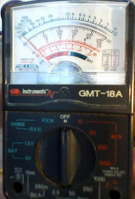
Pictured here is a cheap analog meter I got at Walmart for about $8. It is good enough to do a decent job of troubleshooting most problems.
Most analog meters will be similar in design with variation in scale selection. Even though your meter may not look identical, the features and function will be the same or very similar.
The meter is self contained and portable. There will be a battery compartment that houses a small battery. The battery is used ONLY with the OHMS or resistance measuring function. Voltage measurements are in no way affected by battery condition or even whether or not a battery is included.
The meter has a scale face, a selector switch, a place for lead attachment (red to + and black to -), and an "ohms zero" device. On most small meters, the "ohms zero" is usually a thumb wheel located on the side of the meter.
The meter scale face at first glance can appear intimidating. However, with a little insight, it is pretty simple to understand.
The topmost scale is to read resistance or ohms. More on that later.
Voltage Measurement:
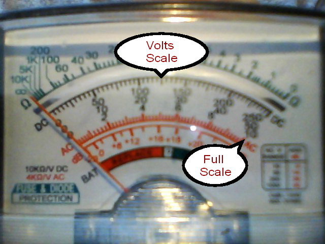
The next scale down is to read voltage, DC or AC. The sub-scale
used for reading is dependent on the selector switch setting. If the selector is
set at "250", then the top voltage scale would be used where full needle
deflection (far right) would be at "250".
If measured voltage caused the needle to deflect exactly midrange with the selector switch set at "250", then the measured voltage would be 125 volts... as read on the upper voltage scale midway between "100" and "150".
Now, if the selector switch is set to "50", for full scale deflection, with the same mid range needle position, the measured voltage would be 25 volts. We would use the next lower voltage scale since the selector is in the "50" position.
Just remember that when measuring voltage the selector switch position notes which sub scale is used. If the selector switch is at "250" the top scale is used... if "10" is selected, the lower scale is used. Your meter may have scales that differ but the same principle applies. The selector switch determines what voltage would cause full scale deflection.
It is good practice to always select the highest voltage scale
to measure an unknown voltage and then lower the scale selection as needed to
obtain a more precise reading. Pegging the meter by having too low a scale
selected may damage it.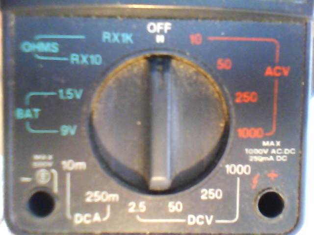
Voltage measurements are usually made with the black probe to ground, preferably battery (-), and the red probe to the test point. A negative needle deflection means the leads are reversed.
DC voltage (Direct Current) is the type voltage used everywhere on a Triple except the yellow leads from the stator which are AC (Alternating Current). Both are read on the same meter face scale. Inaccurate readings can result from having the selector switch in the wrong position for the type voltage being tested.
Resistance, Ohms, Continuity, Measurements:
Resistance is a measure of the opposition to current flow in a circuit.
The unit of measurement is ohms. It is often expressed as K ohms or M ohms... 1K
ohm equals 1000 ohms... 1M ohm equals 1000K ohms. Continuity is the absence of
resistance.
Unlike voltage measurements, the polarity of probes is not a factor except for when a diode (rectifier) is contained within the circuit being tested. A diode's function is to pass freely current flow in one direction while opposing current flow in the opposite direction. So, by design, probe polarity (+/-, red/black) is a factor when testing diode circuits.
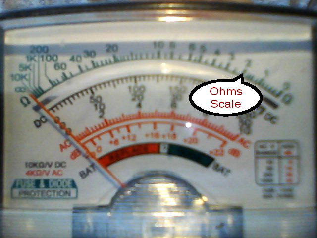
The Ohms scale is read a little different than voltage. It is read directly and then multiplied by the value designated by the selector switch.
For example: If the needle is pointing at the "2" on the ohms scale (as shown) and the selector switch is set at Rx10, then the reading would indicate 20 ohms... 2 x 10.
If the selector was set at Rx1K, the reading would indicate 2K ohms (2000 ohms)... 2 x 1K.
Note that the Ohms scale is not linear. Each hash mark has a value defined by the whole numbers on either side of them.
Before making any resistance check the meter must be zeroed for an accurate reading. This is accomplished by touching the two probes together and adjusting the "ohms zero" thumbwheel or knob until the needle is exactly over the "0" on the ohms scale. The "zero" set when on one selector switch position may not be the same as when another selection is made. For this reason a "zero" needs to be adjusted any time the scale is changed. If the meter batteries are low it will tend to make the difference at zero between scales larger. If the zero cannot be attained by adjusting the thumb wheel/knob then the battery needs to be replaced.
If the selector switch is set for any ohms scale and probes are attached to a voltage source it may result in damage to the meter.
Testing Capacitors (Condensers):
A rough, quick & dirty, test for determining the condition of condensers used on
points systems can be accomplished via use of a resistance check with an analog
multimeter.
-Put the selector switch on a high Rx ohms scale.
-Short the capacitor lead to ground to fully discharge the condenser or close
the points.
-Touch probes across the condenser lead and ground.
-Reverse the test leads and test again.
A good condenser will show a quick needle deflection that will slowly bleed off. A shorted condenser will read near zero with no deflection/bleed off. An open condenser will have no deflection with a reading near infinity.
A Practical Test Example:
Ignition Coil Secondary:
Refer to drawing:
http://kawatriple.com/cdih2/cdih2.jpg
According to the drawing, the secondary of the ignition coil should be 4.5K
ohms.
-Pull the plug wire off the sparkplug.
-Set meter selector to Rx1K and zero the meter.
-Connect meter probes between the metal in the cap and ground.
-Meter should read 4.5.
This tests not only the coil secondary but also all wire connections without
removing the tank.
Ignition Coil Primary:
Refer to drawing:
http://kawatriple.com/cdih2/cdih2.jpg
According to the drawing, the primary of the ignition coil should be 0.8 ohms.
-Pull off the sidecover and disconnect the red wire from the CDI.
-Set meter selector to Rx10 (or Rx1 if available) and zero the meter.
-Connect meter probes between the red wire to the coil and ground.
-Meter should read about 1 hash mark on Rx10 or almost 1 on Rx1.
This tests not only the coil primary but also all wire connections without
removing the tank.
CDI Pickup:
Refer to drawing:
http://kawatriple.com/cdih2/cdih2.jpg
According to the drawing, the pickups should be 200 ohms.
-Pull off the sidecover and disconnect the white wire from the CDI.
-Set meter selector to Rx10 and zero the meter.
-Connect meter probes between the white wire to engine and ground.
-Meter should read 20 on Rx10 setting.
This tests not only the pickup but also all wire connections without removing
the engine cover.
Hi/Low Speed Coil:
Refer to drawing:
http://kawatriple.com/cdih2/cdih2.jpg
According to the drawing, the lo spd should be 200 ohms and hi spd 5 ohms.
-Disconnect the connector from engine with the white and blue wires.
-Set meter selector to Rx10 and zero the meter.
-Connect meter probes between the white wire (lo spd) to engine and ground.
-Meter should read 20 on Rx10 setting.
-Connect meter probes between the blue wire (hi spd) to engine and ground.
-Meter should read 0.5 on Rx10 setting.
CDI Output:
Refer to drawing:
http://kawatriple.com/cdih2/cdih2.jpg
-Pull off the sidecover and disconnect the red wires from the CDI. Mark mating
wires.
-Set meter selector to DC Volts - 250.
-Connect meter probes between a red wire to CDI and ground.
-Turn on ignition key and kick it over.
-Meter should read 50 to 150 volts, depending on kick speed.
-Repeat for each red wire to test all three outputs.
All voltages measured should be the same with the same kick over speed.
This tests the CDI output and lo spd coil function.
Charging System Test:
-Set the meter selector to DC Volts - 50
-Check the battery voltage with ignition off. Red lead to battery (+) and black
lead to battery (-).
A fully charged battery will measure about 12.5VDC.
-Start the engine with lighting off and recheck voltage. As the engine is revved
to 3000rpm the measured voltage should increase to about 14.5-15.5 volts.
-Turn on lights and see that 14.5 VDC can be maintained at 3000rpm.
A voltage measured that is greater than 16VDC indicates a faulty regulator and
can cause battery overvheating and bulb failure. A voltage measured less than
described indicates a component failure, most likely, but not limited to,
rectifier or stator. In some models the rectifier/regulator is a combined unit.