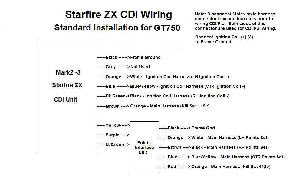
CDI conversion for SUZUKI GT 750 using existing points. The POINTS INTERFACE UNIT must be used with this conversion
1) mount CDI to bike and disconnect battery
2) Disconnect the 6 pin Molex style connector from the 3 ignition coils, and route the main harness end toward the CDI
3) Route the CDI ORANGE, BLUE and DARK GREEN wires to the IGNITION COIL end of this connector and connect these to the WHITE, BLUE/YELLOW and BLACK. (three ignition coil actives, left, center and right)
4) Connect three BLACK wires to the three ORANGE wires in this same connector (common ground), and ground these securely to the frame.
5) Connect the BROWN CDI wire to one orange wire in the rerouted main harness connector as in step 2
6) Connect the BLACK CDI wire to a firm ground.
7) Mount the Points Interface Unit in a suitable place where the three timing lights can be easily seen when setting up the timing.
8) Connect the CDI YELLOW, PURPLE and LIGHT GREEN wires to the Points Interface Unit YELLOW, PURPLE and LIGHT GREEN .
9) Connect the PIU BLACK wire to a firm ground
10) Connect the PIU ORANGE, BLUE and BROWN wires to the WHITE, BLUE/YELLOW and BLACK leads in the Molex style harness connector as in step 2 (left, center and right contact breakers)
11) Connect the RED PIU wire to the ORANGE in main harness connector as in step 2 (ignition 12 volt supply)
The bike will now run.
Note: The GREY wire is used
to disable the ZX MK2 unit. This wire is taken to ground through the
kill, or engine stop switch. This wire can also be used with a hidden
switch as an anti theft, or used with an external rev limiting RPM
counter. Current through this wire is approx 12 milliamps. If not used,
this wire can be cut and ignored.
IMPORTANT: If the ignition key is left on with the kill switch enabled,
the CDI will be in standby mode and still consuming battery power.
Click for Wiring Diagram