The ZX unit, fitted to this model bike gives the
following advantages:
1) Standard fitting in place of the stock unit... small size. Neat installation
using original wiring harness.
2) Brings the complete ignition system up to modern standards, no longer
requiring to use the original unreliable, expensive or hard to replace parts.
3) Converts the system to the early H1 style "battery powered mode."
This eliminates the need for the Hi/Lo Spd high voltage coils which can then to
be used in a future system to run either High Intensity Discharge or Quartz
Halogen lighting with NO FURTHER increases in battery/charging circuit battery
consumption. Additional power consumption here is 12 watts maximum.
For road racing and drag racing applications:
1) The new CDI will run as a simple minimal equipment, stand alone system.
2) Is compatible with external RPM limiting Tachometers
3) Will run 1.5 hours on a small set of AA nicads or similar... total loss
system for weight reduction.
4) Small and light weight.
5) Potentially allows the rotor, and ALL rotating mass to be completely or
partially removed from the crankshaft.
6) User programmable spark intensity for running exotic fuels.
A very simple further upgrade is planned to convert the standard ignition setup
into a full KH400 type system, removing the need for the "low voltage"
distributor on these models.
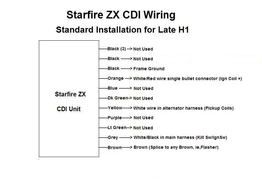
-----------STARFIRE ZX CDI INSTALLATION INSTRUCTIONS FOR Late H1------------
-------- STANDARD FACTORY CONFIGURATION --------.
1) Mount CDI unit to bike
2) Connect the CDI BROWN wire to a source of 12 volts with ignition
key on
(any Brown wire)
3) Connect CDI YELLOW wire to WHITE wire in alternator harness (trigger/pulse
coil)
4) Connect CDI ORANGE wire to WHITE/RED wire in harness
single bullet connector (three ignition coil terminals)
5) Connect one BLACK wire from the CDI to a firm ground
6) Connect the GREY wire from the CDI to the BLACK/WHITE wire in harness
(kill switch)
7) Cut short the unused wires from the CDI , dabbing a spot of nail varnish
on the exposed ends. These are BLACK x 4, LIGHT GREEN x 1,
DARK GREEN x 1, BLUE x1, PURPLE X 1
The bike will now run independent of the High Voltage Stator windings.
The extra current drain is 12 watts maximum at 8000 RPMs.
Click for
Pictorial Diagram
---------MINIMAL CONFIGURATION for dragracing/ roadracing applications.--------
For minimal equipment drag racing/road racing use, The Starfire CDI will
function as a complete stand alone unit. It is suggested a small battery
pack be used to supply the required voltage. A pack of 8 2000 mAh AA
rechargeable NiMh or NiCads will run the unit for approximately 1.5
hours. The GREY INHIBIT wire will cut the engine immediately when
grounded, and will allow an external RPM limiter to be easily connected
to the system. This unit also allows the removal, completely or
partially, of the rotor to reduce the rotating mass on the crankshaft.
Wire the CDI as follows:
1 ) mount the CDI unit to the bike
2 ) connect one CDI BLACK wire to a firm ground.
3) Connect the CDI ORANGE wire to the ignition coil primary,
POSITIVE side.
4) Connect the ignition coil negative to ground
5) Connect the CDI YELLOW wire to the trigger /pulse coil.
6) Connect the CDI BROWN wire to a kill switch or deadmans.
7) The other side of this switch is connected to the battery supply.
8) The GREY wire when grounded will cause immediate
engine shutdown.
This wire can be used with an external rev limiting tachometer, or
ignored.
The bike will now run.
-----------ULTIMATE CONFIGURATION------------
It is hoped that a modification kit will soon be produced to convert
this model into a similar system to the KH400 , doing away with the
existing low voltage distributor setup. Any moving parts that can be
dispensed with is a plus. This kit would only require the addition of
two additional pickup/pulse coils, and an easily modified rotor magnet,
the mods being relatively inexpensive, and simple to perform.. The
Starfire universal CDI is already " future proofed" to cope with this.