Regulator/Rectifier Conversion (Early H1)
Looney Cylinders wrote:
Gents,
After getting too greedy for a decent headlight (and being left on the side of
the road with the ensuing $123.00 tow bill) I came up with the following
charging system option. I have been running this for the last couple of weeks
with good results so far:
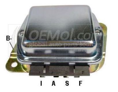
Regulator: Standard Motors VR166 (Ford)
For those who want to use this system I highly recommend using quality parts. There are cheaper off shore parts that are clones and less $$ but the quality may be questionable. Before finding the domestic produced (at that time) regulator I saw a unit that looked almost identical but was not potted. Without potting I suspect it would fail in short order on a Kaw due to vibration and/or moisture.
Rectifier: Delco Remy (US produced) from a 27si type 200 (100 amp?) alternator. I was told the pn is 10456313 or 10497177. I got this unit (new) with another regulator wiring plug for Can$25.00 (Edit: 10SI Rectifier is also acceptable)
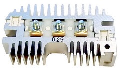
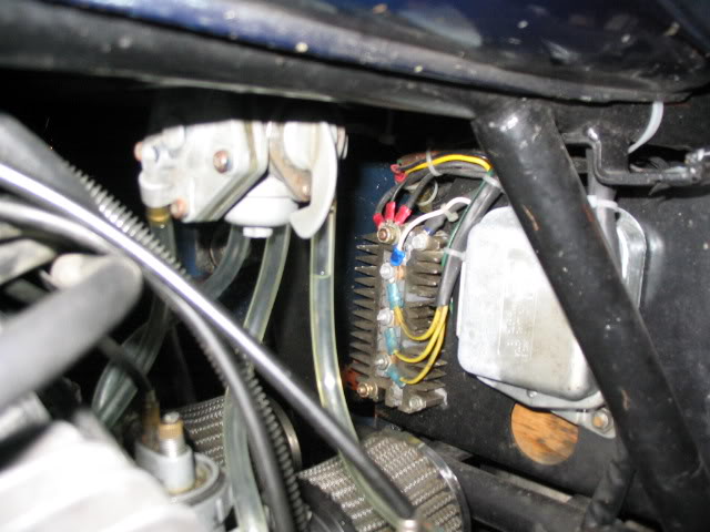
The rectifier unit is a finned unit about 2 3/8 x 4 x 1in. I mounted it on the
front right side of the battery box and the regulator beside it on the front
left side (pod filters are used so this space is available)
WARNING!!!
Half the exposed rectifier is electrically hot so should be painted with
insulating varnish or great care that nothing comes in contact with it. Perhaps
a perforated plastic shield (too allow cooling ) could be fitted?
Wiring at the regulator:
I - (indicator) connected to light blue wire in main harness to the idiot light.
A- (power) connected to switched brown (power) wire in the main wiring harness
S- (stator) connected to any one of the three stator terminals on the rectifier.
F - (field) connected to the green field control wire in the engine wiring loom.
The black field ground wire should be connected to the base of the regulator.
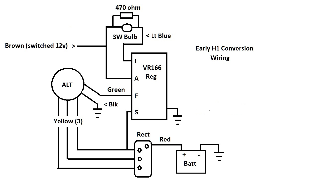
Note: A good charging indicator bulb is required for this regulator to work properly. If the bulb fails the regulator will not function. Adding a 500 ohm resistor in parallel with the bulb will negate the need for a good bulb.
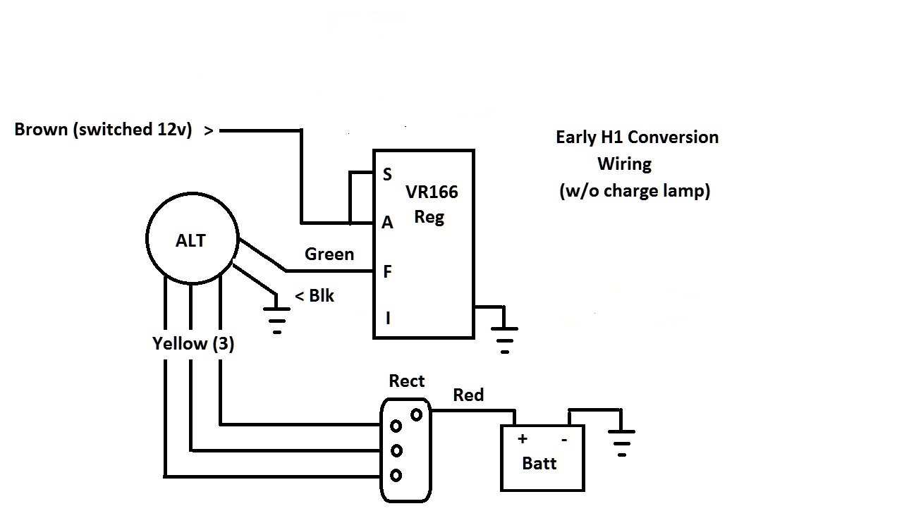
If the modification is to be performed without using a charge indicator bulb (as with H1B) the wiring must be modified. Do NOT attach a wire from the stator to the "S" terminal. Instead, attach a jumper wire between the "S" and "A" terminals and ignore wiring the "I" terminal.
Click Here for Pictorial Wiring
Diagram w/charge lamp
Click Here for Pictorial Wiring
Diagram w/o charge lamp
Rectifier Wiring:
The rectifier half with the raised ears at either end (and insulated on the
back) is the positive side of the rectifier pack. Thread one of the holes in the
ears and electrically connect to the positive side of the battery.
The three yellow stator wires are individually connected to each of the three
posts on the rectifier.
The rectifier unit is mounted and grounded by slotted holes on the negative side
of the rectifier using 10/32 bolts to the battery box. I bonded the rectifier
ground, the regulator ground, and the battery ground together as backup to the
mounting bolts of these units.
The system is essentially wired as an early Ford system. It runs about 13.4
volts with headlight on. Engine off, and no load, the battery voltage is 12.8 to
12.9 volts after an hour of running with lights on.
The early H1 will still not be able to supply a 55/65 watt headlight bulb, but a
35/35watt H4 halogen can be used with a 7in headlight conversion.
I have also fitted an LED 1157 replacement tail lamp that draws very little (
with engine not running you can't even hear a pitch change of the "B" box with
brake light applied) to minimize power consumption.
This is working fine for me and cleans up the Kaw wiring nicely. However, those
that choose to try this wiring option do so at their own risk!
J