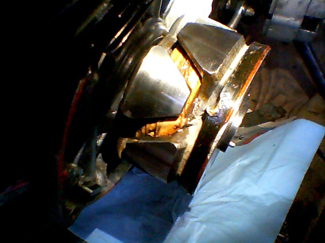
| Attached are pics of a practice rotor. I don't have any pics of my operational rotor as it is buried in the alternator. The mod has held up to my abuse for 4 or 5? seasons. 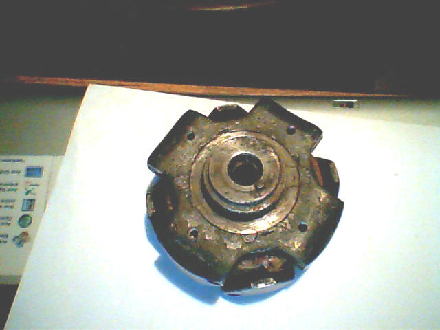
The 4 equally spaced screw holes are offset from the center line of the 4 steel fingers of the steel body about 4mm, opposite of the direction of rotation. This was done to give the best amount of phenolic between the new holes and the existing rivet holes (that holds the steel slip rings to the phenolic).
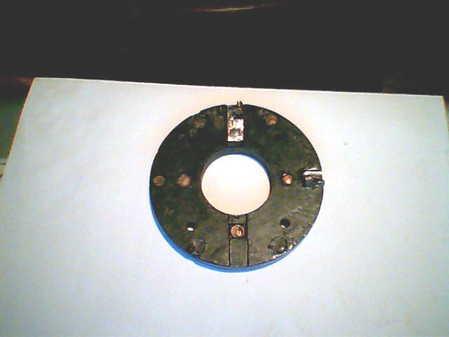 
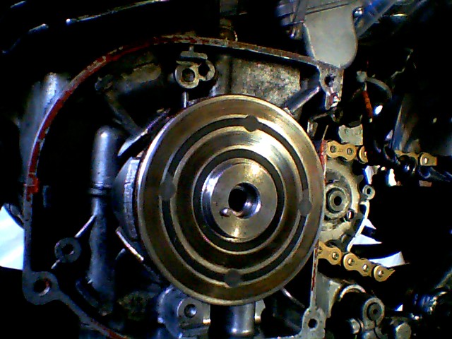
(The outer steel slip ring is held on by 6 rivets through the bakelite. One of these rivets holds one of the terminals. The inner slip ring is held on to the bakelite with 4 rivets. One of the terminals is attached to one of the inner ring's rivets. The other inner rivet locations may be determined as being exactly opposite the wire terminals. The outer rivets can be seen near the circumference of the bake lite ring).
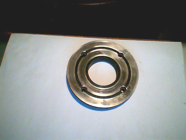
The steel casting is threaded with 8/32 threads to accept the screws (blind holes). The holes in the phenolic are clearance holes. Each hole in the commutator was countersunk deep enough so the head of the screw sits slightly below the steel slip rings to avoid a short circuit. The screw head was reduced in diameter to about .250" to fit the countersunk hole. I used 100 degree aircraft countersunk screws and a matching .250" countersink tool. Be careful you don't drill too deep and hit/ cut the windings!
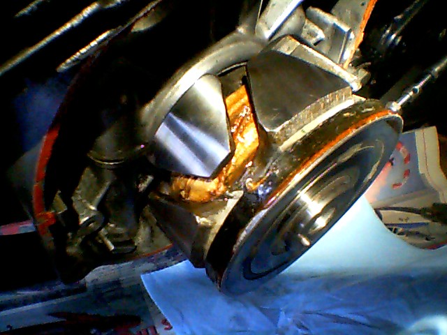
Modding a known good rotor, the old brown glue was removed by carefully levering the slip ring SLIGHTLY away from the steel casting enough to insert a thin knife blade. Be careful you don't break the two feed wires!!!
After you get the old glue out clean it out with contact cleaner. To re-glue the slip ring I used JB weld thinned with acetone and worked it between the steel and the phenolic commutator by gently opening and closing the joint. Try to end up with an even fillet all around the rotor to maintain balance.
I used loctite on the screws. When assembling it (with the glue already applied) mount the rotor on a crankshaft and use the screw tightening to get the slip ring to run true (using a dial indicator). This must be done before the JB weld cures!. Finally fill the screw heads/holes with JB weld. Once cured use a flat file with 400 grit paper wrapped around it to smooth the hole voids flush with the slip ring.
The rotor has endured excessive RPMS many times that would have destroyed an un modded rotor. (Better than 10 grand to date)
The slip ring is still secure after about 20,000+kms/ 5 seasons of my abuse.
Upon close examination there are some very fine cracks developing in the epoxy joint but everything appears to be still tight. I suspect the cracks may be inevitable, as the steel casting heats/expands at a different rate than the phenolic slip ring.
I also looked at a late KH500 style rotor (that's slip ring comes glued and screwed from the factory). It's glue joint is also fractured when inspecting with a 10X magnifying glass.
J Scott C
|