Triple Maintenance Manual
Section 7 - Electrical System Service
This chapter describes the construction, operation, and service procedures
for the motorcycle's electrical equipment, including the charging, ignition, and
lighting systems as well as the warning devices. First, charging-system service
is covered for each of the three basic systems used on the different models, in
chronological order of their development. Then the various ignition systems are
covered in order of increasing sophistication. Finally, the lighting and warning
devices used on these machines are covered. In the end of the chapter is a
specifications table for the electrical systems of all Kawasaki triples.
CHARGING SYSTEMS
The charging system on any motorcycle must perform one basic task; supply enough
electrical power to satisfy the needs of the other electrical systems on the
motorcycle. To do this, the heart of the charging system, the alternator, is
driven by the engine. Some of the engine horsepower is absorbed by the
alternator and converted to electrical energy. Some of this energy goes to the
battery, some to the lighting system, and some to supply current for ignition.
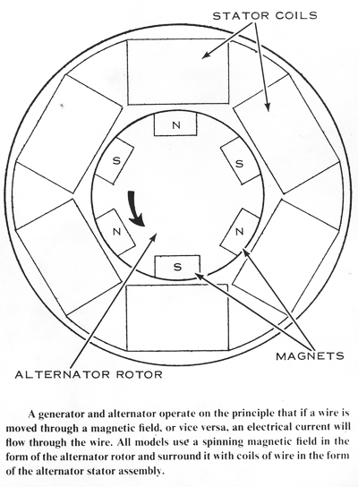
Operation of the alternator is made possible by movement; if a wire is moved
through a magnetic field, or if a magnetic field is moved past a wire, an
electrical current is generated in the wire. All that happens in the alternator
is that a magnetic field, formed by the alternator rotor, is rotated inside
several interconnected coils of wire. These, known as the charging coils, are
wrapped around core pieces of laminated steel plates. The core pieces help
direct the spinning magnetic field to make it more effective.
Every magnet has a north and a south pole. If the magnetic field around a magnet
could be seen, it would look like lines of force moving out of the north end,
curving around the length of the magnet, and entering the south end. As the
alternator rotor turns, it sweeps its north and south poles alternately past
each charging coil. When a north pole passes a given coil, it induces a current
in one direction. When a south pole passes the same coil, it induces a current
in the opposite direction.
Electrical current flows from a "negative" to a "positive" area. That is,
electrical current is the flow of electrons with a negative charge from an area
of high electron concentration (therefore a "negative" area) to one of low
concentration (therefore a more "positive" area, relatively speaking). Thus,
because the current in the charging coils flows in two directions alternately,
the ends of the wires coming from the charging coils are said to change
polarity, from negative to positive.
This "alternating current" or AC from the alternator raises a problem. The
battery to be charged by the alternator is a "direct current" or DC device. It
has a negative lead and a positive lead, making it incompatible with the
alternating current produced by the alternator. This compatibility problem is
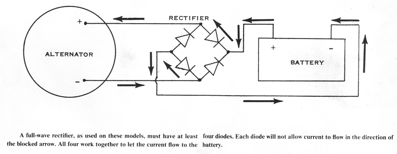
solved by a rectifier. On Kawasaki triples, the rectifier is a solid-state
device, made up of four, six, or nine silicon diodes arranged in such a manner
as to change AC into DC. It does this by electronically switching the
connections from the charging coils to the battery so that they are always
connected in the right direction to charge the battery, no matter which way the
alternating current in the charging coils is flowing. The rectifier's individual
diodes accomplish this by allowing current flow in one direction only. Current
will not flow through a diode in a reverse direction.
The voltage regulator, working with the alternator and rectifier, controls the
output of the charging system. Because the alternator must be designed to put
out enough power to satisfy the whole electrical system's needs at low engine
speeds, its output at high speeds must be
controlled by a regulator or it would overcharge the battery and burn out the
lights. The regulators on these motorcycles are of only two basic designs,
though they all look different.
The battery itself is a 12-volt. lead-acid type of battery. It has 6 cells, each
rated at 2 volts, wired in series. That is, the positive lead of one goes to the
negative lead of the next, and so on, so that the total cumulative voltage is
12. The amperage capacity of the battery depends on the physical size of each
cell. The H1 models have the largest battery, with a rating of 9 amp-hours. This
is an arbitrary rating that gives us an idea of its relative endurance under a
given electrical load. The other Kawasaki triples have a 5.5 amp-hour battery
because their ignition systems do not require as much current as do those of the
H1 models. When replacing a battery, be sure it has an adequate amp-hour rating
or it will soon be exhausted.
H1, H1A. H1B, H1C MODEL CHARGING SYSTEM
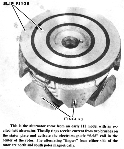
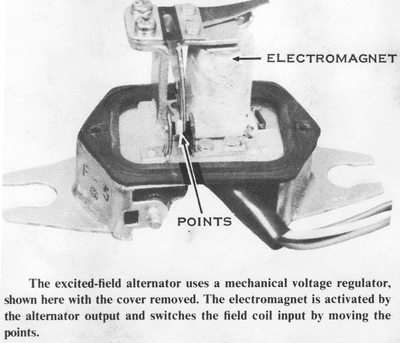
The charging system of these models has an excited-field type of alternator; the
alternator rotor is not a permanent magnet. This rotor has two pole pieces, one
on the front and one on the back. whose "fingers" curve over the edge of the
rotor. As the rotor turns. the coils around it on the stator are exposed first
to a finger of the north pole piece, then one of the south pole piece, and so
on. A large electromagnetic field coil is wound around inside the pole pieces.
The field coil is powered by the rest of the electrical system via two brushes
that ride on slip rings in the outer face of the rotor.
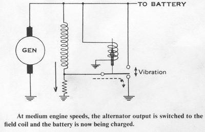
The alternator brushes are connected by a green and a black wire to the voltage
regulator. The voltage regulator has a solenoid-operated switch that controls
the source of power to the rotor. Less power to the rotor lowers its magnetism,
thus lowering the output of the alternator. Increasing the power to the rotor
increases its magnetic field strength and the alternator output rises. The
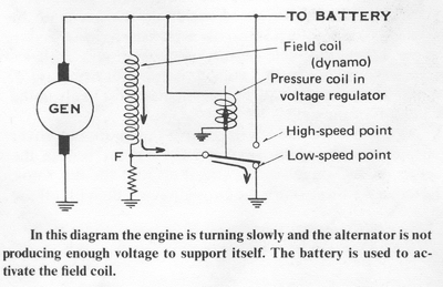
regulator connects the battery to the field coil at low engine speeds to keep
the alternator's output high enough to sustain the ignition system. At higher
engine speeds, some of the alternator's output is siphoned off at the rectifier
to power the field coil. As engine speed rises. the alternator's output
increases to 14.5 volts. The voltage regulator then turns off the current to the
field coil. Therefore, the alternator output drops immediately, and then the
field coil is "turned on" again. The voltage regulator turns the field coil on
and off rapidly to hold the alternator's maximum output at 14.5 volts. Because
the field coil is initially excited by the battery, this system will not charge
a battery whose voltage has dropped too low.
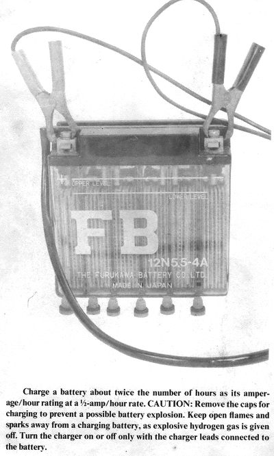
If the battery's voltage is less than 10, remove it from the motorcycle. then
check the electrolyte level. Fill the battery to the upper level line with
distilled water only. CAUTION: If nondistilled water is used, the battery's
life will be reduced by sedimentation shorting the plates. Charge the
battery at a 1/2 amp-hour rate for 15 to 20 hours, with the caps removed.
CAUTION: The caps must be removed during charging to prevent a dangerous buildup
of hydrogen gas inside the battery. Charge the battery only in a well-ventilated
area. Hydrogen gas is very flammable.
The alternator has three charging coils wound on laminations around the
stator and wired together in a "wye." Each coil is joined on one end to a center
(or neutral) connection. The other end of each coil is connected to a yellow
wire. All three yellow wires go to the rectifier.
The rectifier has nine individual diodes arranged in three groups of three. The
rectifier is a nonserviceable unit; the diodes cannot be replaced. Besides the
three yellow wires, there are three other leads on the rectifier. The black
(negative) wire is a ground lead. The blue lead goes to the voltage regulator to
supply current to the field coil. The red (positive) lead goes to the battery to
charge it.
TESTING THE ALTERNATOR
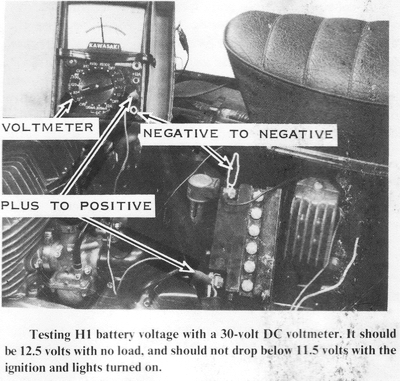
If you suspect that the alternator is not charging the battery, the first test
is a voltage check of the battery with the englne running. Connect a DC
voltmeter across the terminals of the battery without disconnectlng the battery
leads. The meter must have a range of at least 15 volts. The battery voltage
with the main switch OFF should be at least 12 volts. A fully charged battery
will be about 12.5 volts. If the voltage is less than 12 volts, remove the
battery, fill it with distilled water, and then charge it at a rate not
exceeding 1 amp for several hours. If the voltage is less than 10 volts. charge
the battery at a 1/2 amp-hour rate for 15 hours before continuing the test. With
a fully charged battery, start the engine. The voltage with the engine at idle
speed should be about 11.5 volts. This is because the alternator does not supply
enough power at this speed to supply the needs of the ignition system fully.
Gradually increase engine speed to about 4.000 rpm. The battery voltage should
with increased speed rise to 14.5 volts. If it does not rise that far, or if it
does not rise at all, the problem is most likely in the windings of the field
coil.
To check the field coil, remove the alternator cover on the left side of the
engine. Take out the bolt in the center of the signal rotor, and then pull off
the rotor. Remove the three stator mounting screws, then lift off the stator.
Hook the stator over the shift pedal. Check the slip rings on the face of the
rotor for oil or dirt that could prevent the brushes from making good contact.
The most common cause of rotor failure is overrevving the engine. At high engine
speeds, centrifugal force on the rotor's field coil windings is considerable.
The result is failure of the rotor because the winding is stretched and either
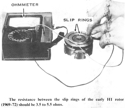
shorted or snapped by the tremendous force. Use an ohmmeter to measure the
resistance between the two slip rings, which should be 3.5 to 5.5 ohms. If the
resistance is infinite, the windings have snapped. If the reading is zero, the
windings are shorted. The resistance between either slip ring and the pole
pieces, or the core of the rotor, should be infinite.
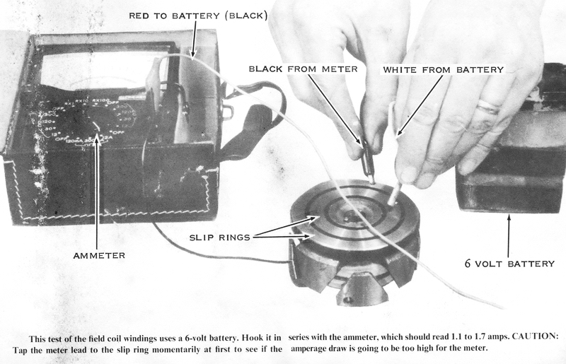
Sometimes a defect will occur only under load. To test for this, hook a 6-volt
battery in series with an ammeter; that is, connect the positive lead from the
battery to the positive lead of the ammeter. Hold the negative lead from the
battery against one slip ring. CAUTION: Use only a 6-volt battery. A 12-volt
battery will ruin the field coil windings. Momentarily tap the negative lead
from the ammeter against the other slip ring. If the needle swings wildly across
the face of the meter, the field coil is shorted. CAUTION: Do not hold the
meter lead to the slip ring under these conditions, or the meter will be
damaged. If the needle moves slowly, hold the connection until the needle
stabilizes. It should read 1.1 to 1.7 amps. A lower reading indicates an open
circuit.
Another load test also uses a 6-volt battery. Hold the leads of the battery
across the slip rings, one to each ring, for 30 seconds. Remove the battery,
then measure the resistance across the slip rings. It must be 3.5 to 5.5 ohms.
This test heats the rotor windings to near their normal operating temperature
for more realistic results.
Other rotor problems do not occur very often, but they can be hard to find if they do. Check that the slip rings are not loose or dented. The wires from the slip rings to the coil can also come loose. They must be soldered in place, or the alternator will not charge. Dirty slip rings should be cleaned with trichloroethylene and #000 steel wool. Very rarely, one of the pole pieces will twist on the core and touch the other. This will cause a magnetic short. CAUTION: Never insert a screwdriver or a bar into the rotor pole pieces to keep the crankshaft from turning. You could twist the pole pieces. When they are twisted, the field coil windings will be broken, and the rotor will have to be replaced.
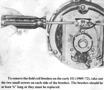
To check the brushes, remove the two screws holding the brush assembly to the stator plate. The brushes are 14mm (9/16') long when new. The service limit is 9mm (3/8"). If either brush is shorter than this, the brush assembly must be replaced as a unit.
In order to generate electricity, the three charging coils must be connected
together. Use an ohmmeter to check for continuity between all three coils.
Remove the left-side cover under the seat, then disconnect the large plastic
plug with the three yellow wires, which are the ones from the charging coils.
Test the continuity between each of the yellow wires and the other two. The
ohmmeter should read zero. If the reading is greater than that between any two
of the leads, the stator assembly must be replaced.
TESTING THE REGULATOR
If the alternator passes the checks described above, you must test the regulator
next, because it is the next most likely component to break down. The basic
regulator check is to test the resistance of the coil in the solenoid that
controls the current flow to the field coil.
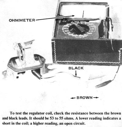
Remove the left-side cover under the seat. The regulator is fastened to the rear
of the battery box. Disconnect the three-prong plastic plug and the single
connector. Use an ohmmeter to measure the resistance between the brown wire and
the black one to check the solenoid coil. The meter should register 53 to 55
ohms. If it is greater than this, the coil has an open circuit. If it is lower
than this, the coil has a short circuit. In either case, the regulator must be
replaced.
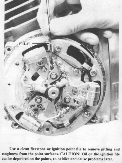
If the regulator has checked "good" so far, remove the two screws holding the
cover on the regulator. Visually check the point set for pitting, burning, dirt,
or oil. File the points carefully on both sides with a clean flexstone or small
ignition file. Clean the points thoroughly with a business card soaked in
trichloroethylene. Pull a dry card through the points until it comes out clean.
Now reassemble the regulator and the alternator, then retest the battery voltage
at 4,000 rpm. If there is still no voltage increase as speed rises, you must
test the rectifier.
TESTING THE RECTIFIER
The rectifier is checked by testing the conductivity of the individual diodes.
Remove the left-side cover beneath the seat. The rectifier is near the regulator
on the back of the battery case. Disconnect the leads and use an ohmmeter to
test the continuity between them. The meter should show infinite resistance in
one direction and no resistance in the other. Connect the negative lead to the
black wire and the positive lead in turn to each of the three yellow wires, the
blue wire, and the red one. The meter should read zero each time. Now connect
the positive lead to the blue wire and the negative lead, in turn, to each of
the yellow wires; connect the positive lead to the red wire and the negative
lead to each of the yellow wires, in turn. Again, all the readings should be
zero. If all these tests register infinite resistance, the batteries in the
meter may be reversed. Try the tests again with the meter leads switched. If all
the readings are now zero, the rectifier is good. However, if any readings are
different from the others, the rectifier is defective and must be replaced.
The checks described so far test the major components of the charging system. If
you still have trouble check every wire for continuity along its entire length.
Make sure every soldered connection is solid and that the multiple connections
aren't missing any pins. Check that the engine is well grounded to the frame.
Clean any corrosion off the battery terminals, and be sure the battery leads are
making a good connection to the battery terminals.
S-SERIES MODEL CHARGING SYSTEM
The charging system of the S-series features a permanent-magnet type rotor and a
solid-state voltage regulator. The alternator's stator has three charging coils
arranged in a "delta" circuit. That is, they are all connected together
end-to-end in a triangle. The leads to the rectifier are connected to the
corners of the triangle. This alternator has no field coil and no brushes. The
field is fully sustained by the permanent magnets in the rotor which makes the
S-series alternator very reliable and inexpensive, but it is not capable of as
much output as the excited-field alternator of the early H1 models. This is not
a handicap, however, because the S-series ignition system does not require as
much power.
The rectifier has 6 diodes. It does not need 9 like the early H1 models, because
there is no power takeoff for the field. The rectifier is a nonserviceable unit;
individual diodes cannot be replaced.
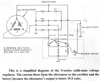
The voltage regulator is a solid-state unit. It has no moving parts and
cannot be disassembled. The basis of this voltage regulator is the combination
of two semiconductor devices, a Zener diode and a thyristor (or
silicon-controlled rectifier, SCR). The Zener diode, like all diodes, wants to
pass current in one direction only. But a standard diode will pass current in
the other direction if the voltage is high enough. Unfortunately, this will
destroy it. The Zener diode, however, is capable of passing a current in the
"wrong" direction without being damaged when the voltage reaches a certain
point. Thus, a Zener diode with a "breakdown voltage" of 15.5 volts is used to
sense when the alternator, output reaches this predetermined maximum. The
thvristor (SCR) is a diode that won't conduct at all until a small voltage is
applied to its "gate" lead. When the thyristor has been "gated" or activated by
a voltage to its gate lead, it will pass a current only in the forward
direction, and then only until the current tries to change direction. Then it
will become nonconductive until it is gated again. The gate signal need only be
momentary. The thyristor is simply an electronic switch.
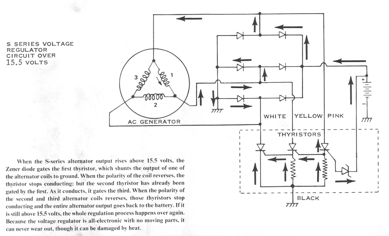
The Zener diode and thyristor work together in the voltage regulator like this;
When the voltage across the battery reaches 15.5 volts, the Zener breaks down
and conducts in a reverse direction. But it is connected to the gate of a
thyristor. The thyristor is connected to one of the three outputs from the
alternator, and it sends that output to ground instead of through the rectifier
for charging the battery. As soon as alternator current begins to flow through
it, two things happen in quick succession; first, the current gates a second
thyristor, then the output from the alternator reverses (its output is AC) and
the first thyristor stops conducting. The second thyristor grounds another of
three outputs from the alternator. At the same time, it gates a third thyristor,
and then turns off as the current direction reverses. The third thyristor
grounds the third output of the alternator, and when that output reverses
direction, it too stops conducting. Now the entire alternator output can go
through the rectifier to charge the battery. But as soon as its output voltage
rises to 15.5 volts again, the Zener diode breaks down, gating the first
thyristor and starting the whole process over again. Thus, the maximum output
voltage is regulated at 15.5 volts.
TESTING THE ALTERNATOR
The basic alternator test is to check the voltage across the battery with the
engine running. Lift the seat and connect the negative lead of a voltmeter, with
a range of at least 20 volts DC, to the negative terminal of the battery.
Connect the positive lead to the positive terminal. With the main switch OFF,
the battery voltage should be 12 to 12.5 volts.
If the voltage is less than 12 volts (but greater than 10), remove the battery,
fill it with distilled water, and then charge it at no more than a 1 amp-hour
rate for 1 to 2 hours. If the voltage is less than 10 volts, charge the battery
at a 1/2 amp-hour rate or less for about 10 hours before continuing the test.
CAUTION: Remove the battery caps and charge the battery only in a
well-ventilated place. Charging the battery releases explosive hydrogen gas
which must be dispersed into the air for safety. Never allow an open flame or
sparks near a charging battery; this includes the slight spark that occurs when
the charger leads are removed. Therefore, always unplug the charger before
disconnecting the leads.
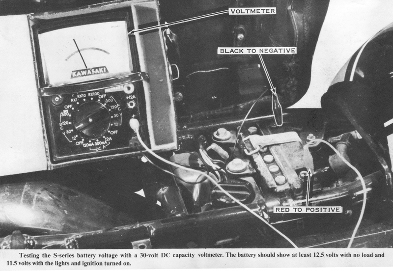
With a fully charged battery, start the engine. The voltage at an idle should be
about 11.5 volts. This is because the alternator cannot supply enough power for
the ignition system at idle speeds. Gradually increase engine speed to 4,000
rpm. The battery voltage should rise to 15.5 volts. If it does not rise that
far, or if it drops, the charging system components must be checked separately
as follows.
The alternator rotor is a permanent magnet. There is no simple test of its
magnetic field intensity, but only extreme heat, on the order of 500° to 600°
Fahrenheit, will cause it to weaken.
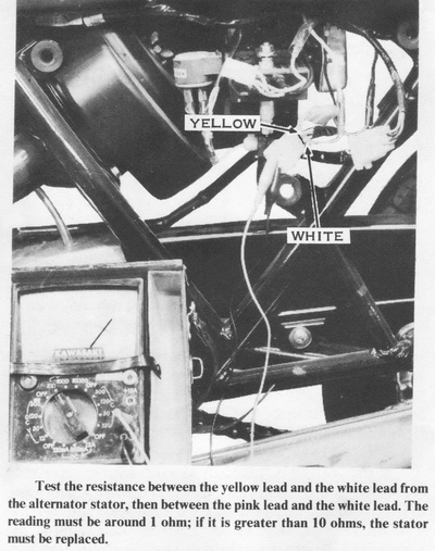
The stator is checked by testing the continuity of the charging coils. To do this, remove the left-side cover below the seat and disconnect the two large plastic plugs, each with a yellow, pink, and white wire. Connect one lead of an ohmmeter to the yellow wire from the female side of one of the plugs (the side connected to the alternator), and then touch the other lead to the pink wire and then the white wire. There should be very little resistance, less than one ohm. Now connect one lead to the pink wire and touch the other to the white. There should be very little resistance here also. If either of these tests shows a resistance of over 10 ohms. the stator assembly must be replaced. Now remove the alternator cover on the left side of the engine. Hook one lead of the ohmmeter to the stator frame. Touch each of the three wires (blue, pink and white) from the charging coil with the other lead There should be infinite resistance. Any lower resistance indicates a short circuit to ground; the stator assembly must be replaced.
If the stator assembly fails any of the above tests, it is defective. However,
even if it passes them all, it still can be defective. You must test the other
components of the system to check the stator by the process of elimination.
INSPECTING THE RECTIFIER
The rectifier is mounted on a tab on the frame behind the left-side cover.
Disconnect the single red wire that goes to the battery, the single black wire
connected to ground, and the large plastic plug that goes to the alternator.
Connect the positive lead of an ohmmeter to the black wire and the negative lead
to each of the three yellow wires and the red wire, in turn. In each case, the
meter should register zero. Now connect the negative lead to the red wire and
the positive lead to each of the yellow wires, in turn. In each case, the meter
should register zero. If the meter registers infinite resistance it all the
tests above, its batteries may be reversed. Switch the meter leads and go
through the tests again. If the meter now registers zero on each test, the
rectifier is good. However, if the meter does not read zero consistently or all
the tests, but zero on some and infinity on others, the rectifier is defective
and must be replaced.
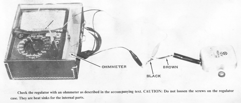
INSPECTING THE VOLTAGE REGULATOR
Because the voltage regulator is a solid-state device it must not be
disassembled and cannot be adjusted CAUTION: Do not turn the screws on the
regulator case They are not adjustments; they are heat sinks (heat-dissipation
points) for some of the internal components. If they are loosened, the
components will overheat and the regulator will fail.
The regulator is fastened to a frame tab near the rectifier behind the left-side
cover. Disconnect the large plastic plug (with the yellow, pink, and white
wires), the single brown wire. and the single black wire. Using short lengths of
small-diameter, bare copper wire, connect the yellow, pink, and white wires in
the regulator side of the plastic plug; these will be treated as one lead in
these tests. Connect the negative lead of an ohmmeter to the brown wire and the
positive lead to the black wire. The meter should register 1,000 ohms or more.
If the resistance is less than this, there is an internal short and the
regulator must be replaced.
Now connect the negative lead of an ohmmeter to the interconnected wires of
the plastic plug and the positive lead to the black wire. The resistance should
be infinite. Now switch the two leads; the resistance should still be infinite.
If it is any less in either test, one of the thyristors is defective and the
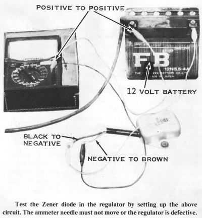
regulator must be replaced. To test the Zener diode, connect the negative lead
of a 12-volt battery to the brown wire and the positive lead of the battery to
the negative lead of an ammeter. Now touch the positive lead of the ammeter to
the black wire. If the ammeter needle is deflected at all from its rest
position, the Zener diode is defective and the regulator must be replaced.
The tests described so far will detect problems in the major charging-system
components. If there are still troubles in the charging system, you must also
check the continuity of all wires and connections with an ohmmeter. There must
be no resistance whatsoever. Make sure every soldered connection is solid and
clean of corrosion. Check that the engine is well grounded to the frame.
NOTE; The engine in S3 models is rubber mounted. There must be a ground wire
from the chain case cover top screw to the frame lug at the upper rear engine
mount. Clean all corrosion off the battery terminals, and be sure the
battery leads are making a good connection to the battery terminals.
If your charging system continually overcharges the battery, boiling the water out of it, the Zener diode breakdown voltage may be too high. The alternator is supplying too much voltage to the system. This can also burn out the lights in a short time. Before replacing the voltage regulator, check the continuity of all wiring and connections with an ohmmeter. There must be no resistance at all. Test the battery voltage at 4,000 rpm. If it is over 16 volts, the Zener diode is bad and the voltage regulator must be replaced.
H1D, H1E, H1F, H2, H2A, H2B, H2C MODEL CHARGING SYSTEMS
In this section two charging systems will be covered together. The H1D and the
H2 models have identical systems. The H1E and H1F models share a slightly
different system. Most of the differences between the H1D/H2 system and the
H1E/H1F system are in the part numbers of the components, many of which look
exactly like their counterparts in the other system.
The alternator has a permanent-magnet rotor that needs no external power source
to activate it. There are four charging coils in the stator, connected in pairs
in series. The two series-connected pairs are connected in parallel. Thus, the
charging coils only have two yellow wires leading to the rectifier.
The rectifier and voltage regulator are built into one unit in these charging
systems. The rectifier/regulator unit is a solid-state type and cannot be
disassembled or adjusted. CAUTION: Do not turn the bolts and nuts between the
cooling fins in this unit. They are not adjustments. They are heat-dissipation
points for the internal components. If they are loosened, the components will
overheat and the rectifier/regulator unit will fail. Although there are
several semiconductor components in the rectifier/regulator unit, the special
components that make up the regulator circuit are a feature of this unit. One is
the Zener diode, which like any diode will conduct only in the "forward"
direction unless a "reverse"' voltage great enough is applied. (Any diode will
conduct in reverse if a great enough voltage is present. but the Zener diode
will not be damaged by this kind of treatment.) The other unique component is
the bidirectional-controlled rectifier, or BCR, a type of electronic switch. It
has a third lead called a "gate" lead. Ordinarily, the BCR will allow current to
flow through it in one direction only. However, when the BCR is "gated" (when it
has had a voltage applied to the gate lead), it will conduct in either direction
until the gate voltage is removed.
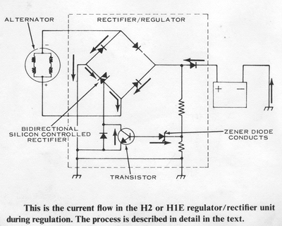
To combine these two special components into a voltage-regulated circuit, a
Zener diode is chosen with a breakdown voltage of 15.5 volts. The Zener diode
senses when the output of the alternator reaches the desired maximum charging
voltage of 15.5. It then breaks down and gates the BCR. The BCR is used in place
of an ordinary diode in the rectifier circuit. The other three diodes in the
circuit are conventional. But the BCR, when it is gated, will conduct in both
directions. and the rectifier circuit can only send half as much current to the
battery as a result. The other half is sent back to the charging coils through
the BCR, conducting in a reverse direction. As soon as the BCR is gated and the
rectifier can send only half the alternator output to the battery, the battery
voltage drops and the Zener diode stops conducting. The no-longer-gated BCR
returns to normal diode function, and the rectifier again sends the full
alternator output to the battery. The cycle starts all over again. By combining
the rectifier and voltage-regulator functions in a single unit, Kawasaki has
made the system less expensive to manufacture and more reliable.
TESTING THE ALTERNATOR

If you suspect that the alternator is not charging the battery, the first test
is a voltage check of the battery with the engine running. Connect a voltmeter
across the terminals of the battery without disconnecting the battery leads. The
meter must have a range of at least 20 volts DC. The battery voltage, with the
main. switch OFF, should be at least 12 volts. A fully charged battery will be
about 12.5 volts. If the voltage is between 10 and 12 volts, remove the battery,
fill it with distilled water, then charge it at no more than a 1 amp-hour rate
for 1 to 2 hours for H2 models, and 2 to 3 hours for H1 models. CAUTION:
Remove all the caps to charge the battery. During charging, the battery gives
off explosive hydrogen gas, which must be dispersed by adequate ventilation.
Keep all open flame or sparks away from the battery. Do not remove the charger
leads while the charger is plugged in; they will spark and can ignite the
hydrogen. If the voltage is less than 10 volts, charge the battery at no
more than a 1/2 amp-hour rate for 10 hours for H2 models, and 15 hours for H1
models before continuing the test. With a fully charged battery, start the
engine. The voltage with the engine at an idle should be 12 volts. Gradually
increase the engine speed to 4,000 rpm. The battery voltage should rise with the
engine speed to 15.5 volts. If it does not rise that far, or if it does not rise
at all, you must inspect each of the components of the charging system
separately as follows.
The alternator rotor has permanent magnets. The brushes and slip rings on the
H1E/H1F alternator rotor are part of the ignition system. The alternator rotor
will not lose its magnetic field intensity unless it is heated to 400° to 500°
Fahrenheit.
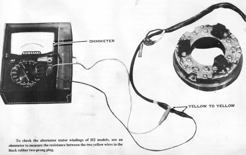
To test the charging coils, remove the left-side cover and unplug the two-prong
rubber connector with the yellow wires. Connect one lead of an ohmmeter to one
yellow wire from the alternator and the other lead to the other yellow wire. The
meter should register 0.4 ohms on HID/H2 systems, and 0.22 to 0.26 ohms on
H1E/H1F systems. If the resistance is higher than this, there is an open circuit
in the charging coils. If it is lower, there is a short within one of the four
charging coils. In either case, the stator must be replaced. Measure the
resistance between the ground and both yellow wires to the alternator. If the
reading is less than infinite, the charging coils are shorted to ground. Again,
the stator must be replaced.
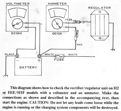
This diagram shows how to check the rectifier/regulator unit on H2 or H1E/H1F models with a voltmeter and an ammeter. Make the connections as shown and described in the accompanying text, then start the engine. CAUTION: Do not let any leads come loose while the engine is running or the charging system components will be destroyed.
TESTING THE RECTIFIER/ REGULATOR UNIT
The design of the rectifier/regulator makes simple resistance checks of its
internal components impossible. The only possible test is to check the
alternator amperage output under various load conditions (lighting, etc.) after
having determined that the charging coils are in good condition.
Remove the left-side cover for access to the rectifier/regulator unit.
Disconnect the red wire to the unit. Fasten the positive lead of an ammeter (of
at least 10 amps range) to the red wire to the unit and the negative lead to the
red wire to the alternator. CAUTION: Be sure they are fastened securely, if
one of the leads were to slip free, the charging system components could be
destroyed in seconds during the following tests. Now connect a voltmeter (of
at least 20 volts DC capacity) across the battery terminals-plus to plus, minus
to minus. Start the engine and let it idle. The ammeter should register less
than 2 amps and the voltmeter 14.5 to 15.5 volts. These readings should be the
same with the engine speeded up to 3,000 rpm. With the engine at idle again,
turn on the headlight low beam. The ammeter should read less than 5 amps; the
voltmeter 12 to 13 volts. At 3,000 rpm the readings should be less than 5 amps
and 14.5 to 15.5 volts. If these readings are not obtained, the
rectifier/regulator unit is not functioning properly and must be replaced.
NOTE: Remember to follow all the charging system tests given here, in the order
in which they are given, before deciding to replace any component.
IGNITION SYSTEM
The motorcycle's ignition system has only one job -to ignite the mixture in the
cylinders at exactly the right instant to produce smooth, economical power. This
may sound like a simple job, but it's not. The spark plugs must operate under
difficult conditions. One end is exposed to the atmosphere at a pressure of
around 14 psi and at a temperature of 50° to 100° Fahrenheit. The other end is
in the combustion chamber exposed to pressures in excess of 500 psi and
temperatures around 1500° Fahrenheit. The electrodes must not burn off after
delivering millions of sparks; the insulator must not break down even though it
must hold back 10,000 to 30.000 volts. The ignition coils must amplify the
voltage of the rest of the system to the over-10,000-volt levels required by the
spark plugs. The timing devices, points or signal coils of the different models
must work at precisely the right instant, thousands of times every minute, to
make the engine run properly.
Every ignition system has four basic components: a power source, trigger or
timing source. high-tension coil, and spark plug. Some systems have more than
one of some of these basic components, but that is only to accommodate the
number of cylinders that must be fired. The power source on three-cylinder
Kawasaki ignition systems is either the battery or a special alternator. The
power source supplies all the electrical power used by the ignition system,
which may be over 100 watts in the most power-hungry system.
The timing devices on these systems come in two basic types. The S-series models
and the H1B have sets of contact breaker points very much like those used in
automobile ignitions. The other models have an electronic signaling device
consisting of a signal rotor on the end of the crankshaft and a signal coil (or
coils) on the alternator stator. This device sends a small pulse of current to
the ignition unit, which allows a capacitor charged by the power source to
discharge to the primary winding of the high-tension coil.
The high-tension coil is similar on all models in that it consists of a pair of
concentrically wound coils, one with few turns (called a primary winding), the
other with many turns (called a secondary winding). The primary has a lead to
the CDI unit or to the points; the secondary has a high-voltage lead to the
spark plug.
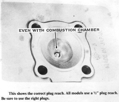
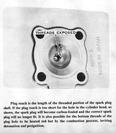
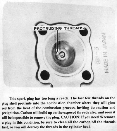
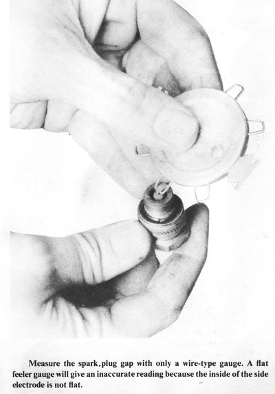
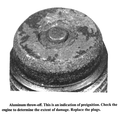
The spark plugs on all models are essentially the same, differing only in
heat range and electrode configuration, except for the surface-gap plugs that
were supplied originally in the H1, H1A, and H1C models. All these models use
1/2"-reach spark plugs. CAUTION: Do not use 3/4"- or 3/8"-reach or
extended-nose spark plugs. Some plugs may hit the top of the piston near TDC
with disastrous results. The exposed threads of others can preignite the
mixture, causing major engine damage. Spark plug recommendations are made at the
end of this chapter.
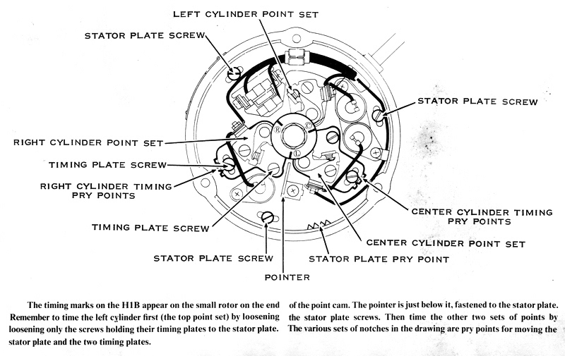
S-SERIES AND H1B MODEL IGNITION SYSTEM
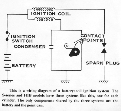
These models use a so-called battery/coil or battery/point ignition system
similar to that used in automobiles for the past fifty years. Actually, these
models have three separate systems, one for each cylinder. A distributor is not
used, nor is there any provision for automatic timing advance or retard under
changed speed or load conditions.
A single-lobe point cam is mounted on the left end of the crankshaft. On the
stator, located around the cam at 120° intervals, are three sets of contact
breaker points. As the crankshaft turns, the cam opens and closes each set of
points in turn. Each set of points is opened and closed once per crankshaft
revolution. One side of each set of points is grounded; the other side has a
wire to the ground wire of one of the high-tension coils. On the S-series
models, the point set wires are color coded as follows: left cylinder, green
wire; center cylinder, black wire; right cylinder, blue wire. On the H1B. the
color code is: left cylinder, green wire; center cylinder, red/white wire; right
cylinder, black wire.
The three high-tension coils are mounted on frame tabs under the front end of
the fuel tank, which must be taken off to remove, replace, or inspect the coils.
Each coil has a brown wire from its primary winding to a common brown wire which
goes to the main switch, where it is connected to the battery. The secondary
winding of each coil has a large black high-tension lead to one spark plug.|
The spark plug is fired, as in any battery/coil system, by the opening of the
points. As long as the points are closed, the battery is supplying current to
the primary windings of the high-tension coil to develop a strong magnetic field
around both windings. When the points open, the current stops flowing in the
primary windings and the magnetic field collapses. The field collapses rapidly
past the thousands of turns of wire in the secondary winding to the soft iron
core, and extremely high voltage is generated, which jumps the spark plug gap.
As the field collapses, it also moves past the primary winding, generating a
smaller voltage in it that tries to jump the point gap, as if it were a spark
plug. If this were
allowed, to happen, the points would soon become burned and pitted by the
arcing. To prevent this a condenser is connected across the points. It "soaks
up" this surge of electricity and helps preserve the points. When the points
close again, current from the battery starts to flow in the primary, rebuilding
the magnetic field around the high-tension coil in preparation for the next
spark.
TIMING THE S-SERIES AND H1B IGNITION
There are two methods of checking the static ignition timing; matching the
timing marks or measuring the piston movement from TDC with a dial indicator.
Matching the timing marks is the simplest method, but it may not be completely
accurate because of production tolerances in stamping the marks and machining
the keyways in the crankshaft and rotor. A bent timing pointer (or shifted
stator plate) can also result in incorrect positioning of the stationary timing
mark. Using the dial indicator eliminates these inaccuracies because the points
are adjusted to open at the exact piston position and, therefore, at the
specified crankshaft angle. The dial indicator can also be used to verify the
accuracy of the timing marks, after which they can be used with confidence.
MATCHING THE TIMING MARKS
Adjust the ignition timing only after having cleaned the points and adjusted
their gap. Attach a self-powered continuity lamp across one set of points by
connecting one lead to any metal part of the engine (ground) and the other lead
to the breaker-arm spring. CAUTION: Make sure the main siwitch is in the OFF
position, or else the lamp will be energized by the motorcycle's battery.
Slowly turn the crankshaft in the normal direction of rotation
(counterclockwise) and watch the continuity lamp, which will go out when the
points open.
If the timing is correct, the points will open just as, the timing mark on the
edge of the rotor coincides with the pointer's mark. If the points open before
the marks coincide, the ignition timing is advanced; if they open after the
marks coincide, the timing is retarded.
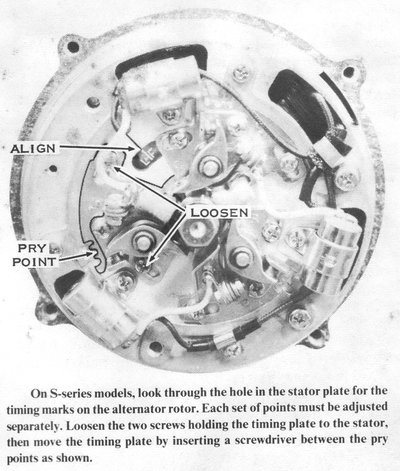
To adjust the ignition timing, loosen the two screws securing the timing plate
by 1/2 turn. Wedge a screwdriver blade between the timing plate notch and the
stator plate dimples. If the timing is advanced, turn the screwdriver clockwise
to retard it; if retarded, turn the screwdriver counterclockwise to advance it.
Tighten the timing plate screws, recheck the point gap. and then recheck the
ignition timing. Repeat the procedure for the other two sets of points. Burnish
the closed point surfaces by drawing strips of lintless paper through until no
trace of dirt or oil is left, and then install the left engine cover.
CHECKING THE S-SERIES IGNITION TIMING WITH A DIAL GAUGE
Remove all spark plugs, then screw a dial gauge adaptor into the left-hand spark
plug hole, leaving the clamp screw loose. Turn the crankshaft with a wrench
until TDC is indicated by the needle's reversing direction. Push the dial gauge
into the adaptor until the small pointer registers 5mm. CAUTION: If the dial
gauge is forced past 5mm, the delicate internal mechanism will be jammed.
Tighten the adaptor clamp screw to secure the dial gauge in this position. Turn
the crankshaft back and forth past TDC while rotating the dial bezel so that the
needle registers zero just as it reverses.
Starting with the crankshaft and piston at TDC (needle at zero), slowly rotate
the crankshaft clockwise. Count the number of rotations of the needle and stop
when the needle indicates a piston drop of 2.60mm. This is exactly 23° before
TDC. The mark on the stator plate near the window (located at 10 o'clock) should
align with the mark near the L on the face of the alternator rotor. If it
does not, make a small scratch mark on the stator plate that does align. Move
the dial gauge to the other two cylinders and repeat the procedure. The ignition
should now be timed (using the corrected timing marks) as described in the
previous section.
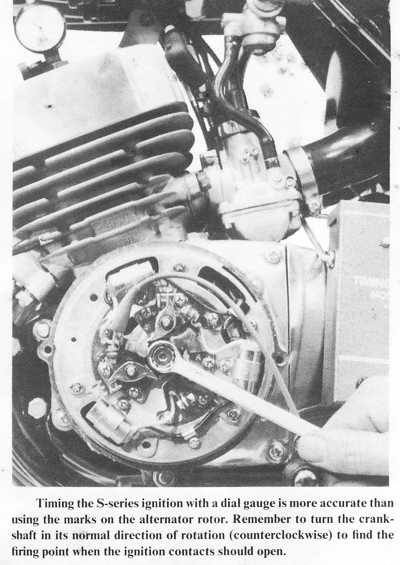
Alternatively, you can use the self powered continuity lamp with the dial gauge
instead of marking the stator. When the crankshaft is rotated counterclockwise,
the continuity lamp should light just as the dial gauge indicates 2.60mm. Turn
the crankshaft counterclockwise to about 2.70mm, then turn it slowly clockwise;
the light must go out as the needle registers 2.60mm. Be sure to move the dial
gauge to the other two cylinders to be sure all three are timed properly.
After timing all three sets of points, replace the spark plugs, the spark plug
wires, and the ignition cover. Be sure to get the right wires on the right spark
plugs.
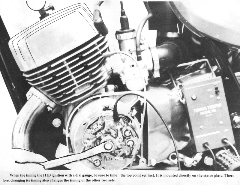
CHECKING THE H1B IGNITION TIMING WITH A DIAL GAUGE
The procedure for timing the H1B with a dial gauge is very similar to the
S-series procedure described above. Remove all three spark plugs, and then screw
the dial gauge adaptor into the left-hand spark plug hole. CAUTION: Do not
tighten the clamp. Turn the crankshaft with a wrench until the needle's
reversing direction signals TDC. Push the dial gauge into the adaptor until the
small pointer registers 5mm. CAUTION: If the dial gauge is forced past 5mm,
the delicate internal mechanism will be damaged. Tighten the clamp screw to
secure the dial gauge in this position. Turn the crankshaft back and forth past
TDC while rotating the bezel on the dial gauge so that the needle registers zero
just as it reverses.
Connect one lead of a self powered continuity lamp to the arm of the movable
point and the other to a good ground such as a cylinder fin. CAUTION: Be sure
the main switch is turned OFF or the motorcycle's battery will light the lamp.
Starting at TDC, slowly rotate the crankshaft clockwise. Count the number of
rotations of the needle and stop when the needle indicates a piston drop of
2.23mm. This is exactly 20° before TDC. The lamp should light. Turn the crank
past this point to about 2.40mm. Now turn it counterclockwise until the dial
gauge indicates 2.23mm. The light should go out at exactly this point. If it
does not, loosen the three stator plate screws and move the entire stator plate
until the light goes out at exactly 2.23mm. Tighten the stator plate screws
securely, and then check the timing again. Now move the dial gauge to the other
two cylinders and repeat the procedure with the following difference: When
setting the timing of the center and right-hand cylinders, do not loosen the
stator plate screws; loosen only the two screws holding that one set of points.
After timing all three sets of points, check that the point gaps are still
between 0.012" and 0.016" Replace the spark plugs, spark plug wires. and
ignition cover. Be sure to get the right wires on the correct spark plugs.
TROUBLESHOOTING THE IGNITION SYSTEM-S-SERIES AND H1B MODELS
If the engine does not run at all, check for a spark at the plug electrodes by
laying the spark plug, with its high-tension wire attached, on the cylinder
head, and then try to kickstart the engine. If there is a spark, you must
inspect the other systems of the engine as described in Chapter 1,
Troubleshooting. If there is no spark or if the engine misses at high engine
speeds or under load, you must inspect the components of the ignition system as
described here.
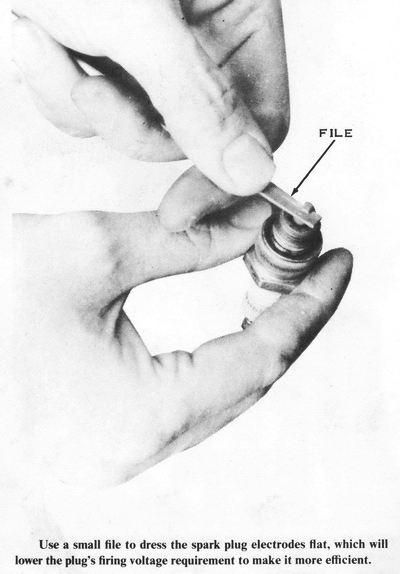
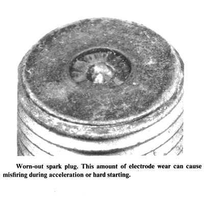
A common part to fail in any ignition system is the spark plug, because of the
extreme conditions of heat and pressure under which it functions. Remove the
spark plugs. The electrodes will be burned and rounded unless the plugs are new.
File the electrodes square, then regap the plugs to 0.020" (0.5mm). Clean the
carbon deposits from inside the plug shell and from around the center electrode.
CAUTION: Never bend or stress the center electrode or its insulator will
break. If the spark plugs have over 2,000 miles on them, you should discard
them. Spark plugs do not last long in these high-output engines.
To inspect the points, remove the ignition cover on the left side of the engine.
Remove all three spark plugs to make the crankshaft easier to rotate. Pry each
of the point sets open with your fingers so you can see the contact points
themselves. The surfaces of the points are flat and smooth when they are new.
After being used for a while they become burned and pitted. If one side is
deeply pitted and the other has a mound built up on it, the condenser is bad and
must be replaced. If the points are not severely pitted, dress them flat with a
clean flexstone or a small ignition file. Clean the points with a business card
soaked in trichloroethylene, then pull a dry card between the points until it
comes out clean. Gap the points and adjust the ignition timing as described
previously. Replace the ignition cover, spark plugs, and wires.
If there is still no spark at the spark plugs, check the high-tension coils and
the spark plug wires. To test the coils, you must first remove the fuel tank.
CAUTION: Make sure the fuel cock is turned to S (for stop), before disconnecting
the fuel hoses. Pull the brown wires and the black wires free of the coils.
Hook one lead of an ohmmeter to the black wire for one of the sets of points and
the other lead to a good ground. Kick the engine over. The ohmmeter should swing
from infinity to zero and back as the points open and close and open again. Test
each black wire this way.
Now connect the positive lead of a DC voltmeter (with a range of at least 15
volts) to the brown wire going into the wiring loom. Hook the other lead to a
good ground. Turn the main switch ON; the meter should read 12.5 volts. If it
does not, check the battery voltage. If the battery voltage is low, you may have
a charging system problem. If the battery voltage is 12 or more, the problem is
in the wiring or the main switch. Use the ohmmeter to isolate the problem.
Check for continuity between all connections and across the main switch in all
positions. Checking the main switch is described in detail later in this
chapter. Finally, connect one lead of an ohmmeter to the black lead from the
coil and touch the other lead to the brown wire and the spark plug wire in turn.
Both should show some resistance but less than infinity.
H1, H1A, H1C MODEL IGNITION SYSTEM
The ignition system of the H1, H1A, and H1C models was the first CDI (Capacitor
Discharge Ignition) system used by Kawasaki. A capacitor is charged by the
battery indirectly, then discharged to fire the spark plug.
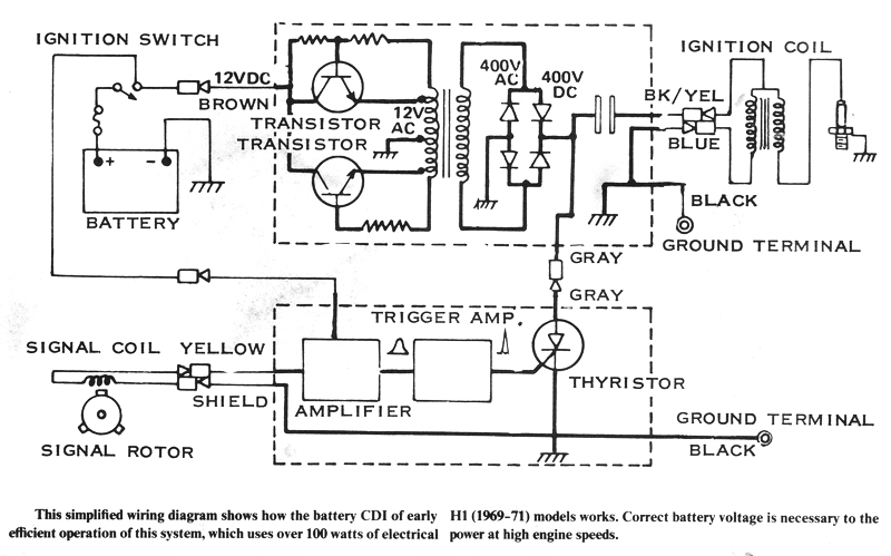
This is how it works: Battery voltage is fed to a transistor oscillator
circuit. In simple terms, this is a circuit that automatically switches the
battery direct current back and forth so that alternating current comes out the
other side. This alternating current, still at 12 volts, is fed to a special
step-up transformer which is very similar to a high-tension coil. The 12 volts
AC goes through the primary winding of the special transformer, and the magnetic
field that rises and falls with every alternation of the current flow direction
induces a current in the secondary winding of the transformer. The secondary
winding, however, has many more turns of wire than the primary winding, so the
voltage is much higher, around 380 to 400 volts AC. This current goes through a
rectifier, and the resulting 380-400 volts DC is used to charge the capacitor,
which will be discharged into the primary lead of the high-tension coil.
A small signal rotor with three magnets in it is located on the left end of the
crankshaft, outboard of the alternator rotor. Mounted on the stator near the
signal rotor is a small black plastic component called a signal coil. As each of
the three magnets in the rotor moves past it, a tiny pulse of current is
generated in the signal coil. The pulse travels through two solid-state
electronic amplifiers which shape its wave-form and increase its strength to
make the timing more precise and reliable at all speeds. The pulse now goes to a
solid-state electronic switch called a thyristor. It will not allow any current
to flow through itself unless it is given a signal in the form of a small pulse
of current. The thyristor then is triggered by the pulse from the signal coil.
When the thyristor conducts, it connects the highly charged capacitor to the
primary winding of the high-tension coil. As the capacitor discharges its stored
energy through the primary winding, a strong magnetic field quickly builds
around the core of the high-tension coil. This rising magnetic field cuts across
the secondary winding, inducing in it a tremendous voltage (up to 30,000 volts)
which arcs across the plug gap. A distributor much like an automotive one
switches the output of the high-tension coil to each of the three spark plugs in
turn.
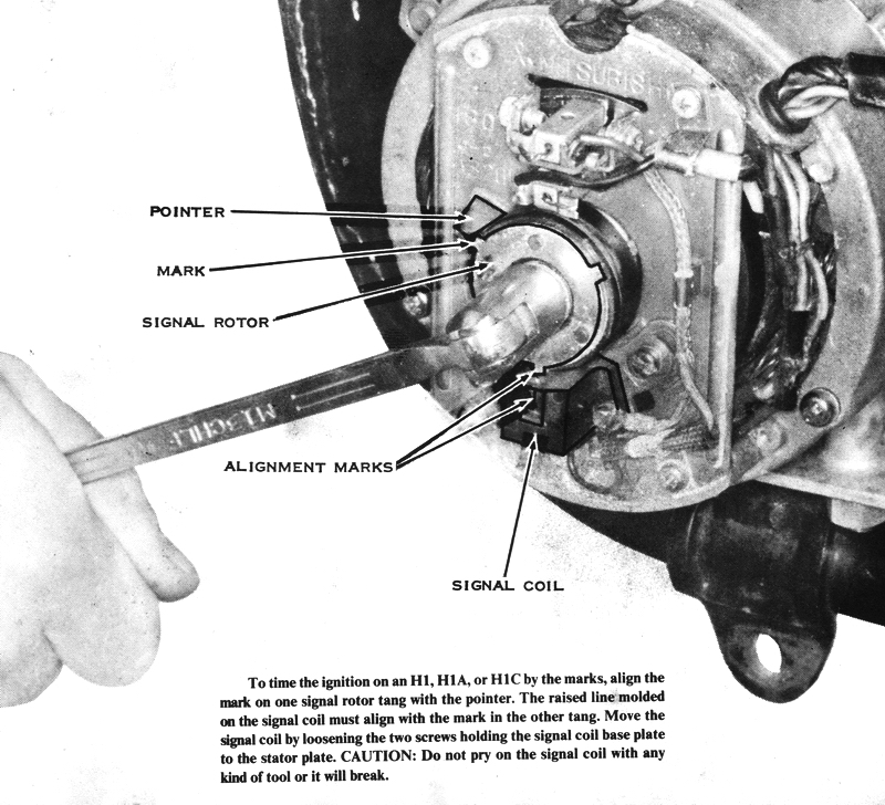
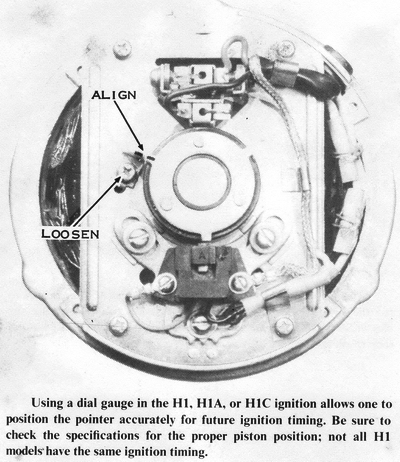
TIMING THE IGNITION SYSTEM-H1. H1A, AND H1C MODELS
MATCHING THE TIMING MARKS
Adjust the ignition timing only after having set the air gap. Turn the
crankshaft until the mark on one of the signal rotor tangs aligns with the
pointer on the stator plate (located at about 10 o'clock). One signal rotor tang
will point straight toward the signal coil. The mark on that tang should align
with the raised line molded on top of the signal coil. If it does not, loosen
the two screws holding the signal coil mounting plate to the stator and move it
accordingly. CAUTION: Do not pry on the signal coil with any kind of tool. It
is very delicate and will break easily. Move it only with your fingers.
Tighten the screws, recheck the timing, and then replace the ignition cover.
TIMING THE IGNITION SYSTEM WITH A DIAL GAUGE
Remove all three spark plugs and the ignition cover on the left side of the
engine. Screw a dial gauge adaptor into the left cylinder spark plug hole,
leaving the clamp loose. Turn the crankshaft with a wrench until TDC is
indicated by the needle's changing direction. Push the dial gauge into the
adaptor until the small pointer registers 5mm. CAUTION: If the dial gauge is
forced past 5mm, the delicate internal mechanism will be damaged. Tighten
the adaptor clamp screw to hold the dial gauge in this position. Turn the
crankshaft back and forth past TDC while turning the dial bezel so that the
needle registers zero just as it reverses.
Starting with the crankshaft at TDC, slowly rotate it clockwise. Count the
number of rotations of the needle and stop when the needle indicates 3.45mm.
This is exactly 25° before TDC. The raised line molded into the top of the
signal coil should align with the mark on the signal rotor tang. If it does not.
loosen the three screws that hold the signal coil base plate to the stator
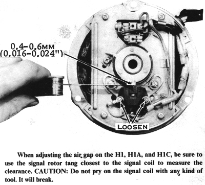
plate, then move the signal coil as required. CAUTION: Do not pry on the
signal coil with any kind of tool. It is very delicate and will break easily.
Move it only with your fingers. Tighten the signal coil base plate mounting
screws. then check the air gap which must be from 0.016" to 0.024". Now loosen
the screw that holds the pointer (located at about 10 o'clock) to the stator
plate. Move the pointer so it aligns with the mark on the closest signal rotor
tang, and then retighten the screw. The ignition can be timed from now on
(without the use of the dial gauge) by just matching the pointer with the mark
as described in the previous section.
Replace the spark plugs, spark plug wires, and ignition cover. Be sure to get
the right spark plug wires on the correct plugs.
TROUBLESHOOTING THE IGNITION SYSTEM-H1, H1A AND H1C MODELS
If the engine does not run at all, check for a spark at the spark plug
electrodes by laying each of the spark plugs, with its high-tension wire
attached, on the cylinder and trying to kickstart the engine. If there is a
spark, you must inspect the other systems of the engine as described in Chapter
1, Troubleshooting. If there is no spark. or if the engine misses at high speeds
or under load, you must inspect the components of the ignition system as
described here.
A common part to fail in any ignition System is the spark plug. because of the
extreme conditions of heat and pressure under which it functions. Remove the
spark plugs. The electrodes will be burned and rounded unless the plugs are new.
File the electrodes square. then regap them to 0.040" (1.0mm). Clean the carbon
deposits f: from around the center electrode. CAUTION: Never bend or stress
the center electrode or its insulator will break.
If the spark plugs are the surface gap type, they do not need to be cleaned or
gapped. Check the surface of the insulator around the center electrode for signs
of tracking, which looks like shiny, radial lines from the center electrode to
the spark plug shell. If the insulator surface is tracked, the high voltage from
the ignition coil will "leak" across the track before it has risen high enough
to jump the gap. NOTE: The two surface gap spark plugs recommended for this
engine are the Champion UL-17V and the NGK BUHX. Generally, the UL-17V will make
the engine run more smoothly at small throttle openings because it has an
extended nose. However, it tends to foul or track more easily than the BUHX
because it has only a 0.200" booster gap (series gap). The BUHX has a 0.250"
booster gap so that the voltage seen at the spark plug electrodes is higher.

After checking the spark plugs, go to the "top" of the system
and work down. To check the CDI units, lift the seat and turn on the ignition
switch. You should be able to hear a high-pitched hum, which is the oscillator
in the "B" unit. If you do not hear the hum, or if it is very faint, check the
battery voltage, which must be at least 10 volts or the engine will not run. If
the voltage is less than 12, the engine may miss at high speeds (if the charging
system is not operating perfectly).
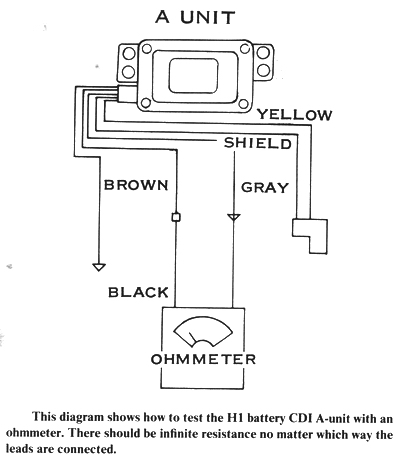
To check the "A" unit with an ohmmeter, first disconnect all the wires to the
"A" unit. NOTE: The "A" unit is the box directly behind the fuel tank under
the seat. Connect the red lead from the ohmmeter to the black wire from the
"A" unit and the black meter lead to the gray wire from the unit. The meter
should read infinity. Switch the leads and try again. There should still be
infinite resistance between the black and gray wires. These tests are not
conclusive; therefore, if the unit fails either one, it must be replaced. If it
passes both tests, it may still be bad. The only way to test it further is by
the process of elimination: if there is nothing else wrong, the "A" unit must be
bad.
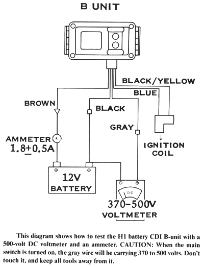
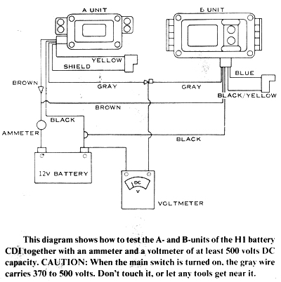
To test the "B" unit with an ammeter and a voltmeter, first
disconnect the brown wire from the "B" unit and the gray wire and the black wire
to the "A" unit. Hook a voltmeter with a capacity of at least 500 volts DC
between the gray wire from the "B'' unit and a good ground. Fasten the positive
lead of an ammeter to the brown wire from the "B" unit and the negative lead to
the brown wire from the main wiring harness. CAUTION: When the ignition
switch is turned on, the gray wire will be carrying from 370 to 500 volts; do
not touch it. Keep all tools away from it. Turn on the ignition switch. The
"B" unit should hum, the ammeter should give a steady reading of 1.3 to 2.3
amps; and the voltmeter should indicate 370 to 500 volts DC. If you do not get
these readings with a fully charged battery, or if the unit does not hum, the
"B" unit is defective and must be replaced.
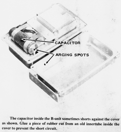
Before discarding a "B" unit that does not pass these tests, remove it from the
motorcycle and take off the cover. Four small Phillips-head screws hold it in
place. Check inside the cover to see if the capacitor (the large light-colored
cylindrical component that is placed across one end of the unit) has shorted
against the cover. If the cover is blackened near the end of the capacitor,
shorting has occurred. The unit is probably salvageable if this is all that has
gone wrong. Glue a piece of rubber from an innertube on the inside of the cover
so that the end of the capacitor cannot touch the cover. Now reassemble the unit
and retest it. If it now checks good, remount the "B" unit. If it still does not
pass the voltmeter/ ammeter test, it must be replaced.
If both units check good separately. but the engine still won't run, check the two units together. To do this, hook all the wires together properly. Disconnect the white wire from the battery to the fuse and insert an ammeter as follows: Connect the negative ammeter lead to the battery side and the positive lead to the fuse end of the white wire. Now attach one lead of a voltmeter with a capacity of at least 500 volts DC to the connector in the gray wire from the "A" unit to the "B" unit. Connect the other lead to a good ground. CAUTION: When the ignition switch is turned on, the gray wire carries 370 to 500 volts; do not touch it. Keep all tools away from it. Turn on the ignition switch. The "B" unit should hum, the ammeter should give a steady reading of 1.5 to 2.5 amps, and the voltmeter should indicate 370 to 500 volts DC. If the units together do not pass these tests they are defective.
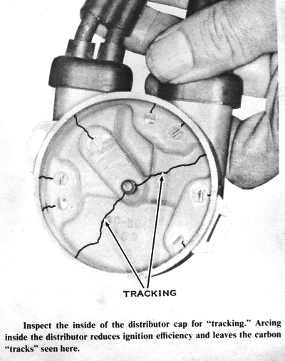
The distributor is located on the right end of the engine under
the aluminum cover. To inspect the distributor, remove the cover. The grommet
that goes around the high-tension wires where they leave the cover should be
free of cracks and should seal well against the cover to keep moisture out of
the distributor. Remove the two screw clamps holding the distributor cap to the
end of the engine. Check the inside of the cap for carbon tracks caused by
internal arcing, which mean that the insulating strength of the material of the
cap has diminished and the distributor cap must be replaced.
Pull the distributor rotor straight off to check it. The brass end will be
burned but will work properly unless both it and the contacts inside the cap are
severely burned. Take off the gasket and the distributor insulator. Check the
insulator for carbon tracks. The gasket must fit the insulator and cap properly
without buckling or stretching. If it has shrunk or shriveled, it must be
replaced.
Inspect the insulation of the high-tension wires carefully for cracks or breaks
that might let the high-voltage electricity leak before the plug is fired.
Broken or frayed insulation will cause high-speed misfiring, and one of the
spark plugs will seem to foul very quickly. If one wire needs to be replaced,
the others should be replaced too. CAUTION: When reassembling the
distributor, be sure to include the gasket and the insulator under the rotor. If
either is left out, the rotor will hit the distributor cap and be damaged.
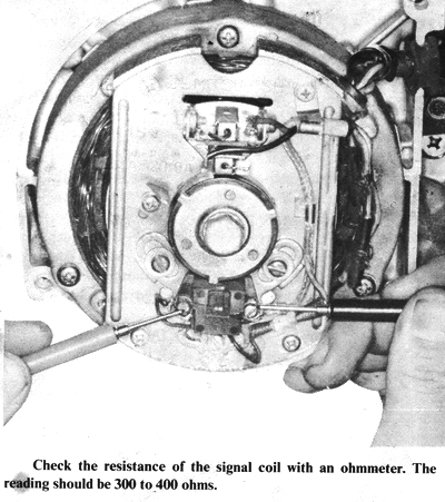
Probably the least likely part of this ignition system to fail
is the signal generator. To check the signal coil, lift the seat, then unplug
the black rubber two-prong plug with the shielded yellow wire. Use an ohmmeter
to check the resistance between the prong and the socket on the engine side of
the connector. There should be 300 to 400 ohms. If there is less, the turns of
wire in the coil are shorted together and the signal coil will not put out a
strong enough signal pulse to trigger the ignition system. If there is excessive
resistance, the signal coil pulse will be reduced before it can trigger the
ignition system. In either case it must be replaced.
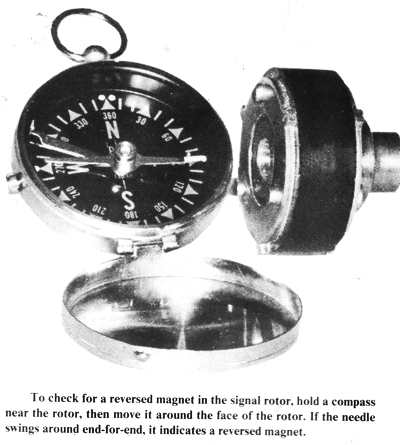
The magnets in the signal rotor are a permanent type and only very high temperatures, as in a gasoline fire, can cause them to lose their magnetism. There have been cases, however, where the magnets have been installed in a rotor improperly. This is not a problem that develops over a period of time, but you might experience it when the rotor is replaced with a new one that has never been used before. To test for a reversed magnet, check the polarity of each of the three magnets in the rotor with a compass. Hold the compass near the outer face of the rotor near the edge, and then turn the rotor slowly. One end of the needle must point to the rotor at all times, provided that all three magnets are installed the same way. If the compass needle reverses itself as you turn the rotor, one of the magnets is reversed and the rotor must be replaced.
If you have installed a rotor with a reversed magnet, your engine will not run
properly because one spark plug will fire about 40° too soon. This will make the
engine run irregularly, and it may kick back very strongly when you try to kick
start it. NOTE: Before inspecting the rotor when these symptoms occur, first
be sure that the ignition is properly timed with a dial gauge.
There is no test for the ignition high-tension coil that will tell you if it is
absolutely good or bad. Use an ohmmeter to measure the resistance between the
high-tension terminal and the negative terminal and between the positive and
negative terminals. If either resistance is less than one ohm, the coil can be
internally shorted. If either resistance is greater than 10 ohms, there can be a
partially open winding. If all the previous tests show the other ignition
components to be in good condition, replace the high-tension coil with a new one
or one from a motorcycle that runs.
H1D AND H2 MODEL IGNITION SYSTEMS
The ignition system used on all H2 models and on the H1D is actually three
separate ignition systems, one for each cylinder, that share only a few common
parts The power source for this CDI system is an alternator on the left end of
the crankshaft. It uses the same permanent magnet rotor as the alternator for
the charging system and has two coils on the same stator as the main alternator.
These two coils are one of the advantages of this ignition system. One coil,
called a low-speed coil, has a great many turns of wire so that it feeds, the
ignition system high voltage even at low engine speeds. The high-speed coil has
fewer turns of wire but less resistance than the low-speed coil. At high engine
speeds, when the voltage from the low-speed coil drops, the voltage from the
high-speed coil is high enough to operate the ignition system. There is no
change-over switch; the high-speed coil takes over from the low-speed coil
automatically.
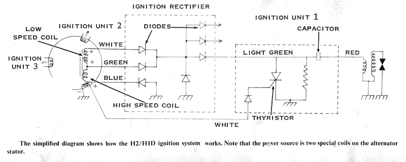
The two coils put out 300 to 400 volts AC to the rectifier unit.
This is a long, narrow box mounted under the seat with the three ignition units.
The rectifier changes the AC voltage to DC voltage and sends it to each of the
three ignition units through the three light green wires. Each ignition unit has
a capacitor in it (among other things), charged to 300 to 400 volts by the
rectifier.
There is a signal generator on the left end of the crankshaft. It consists of
three signal coils on the stator plate and a signal rotor on the crankshaft,
outboard of the alternator rotor. The signal rotor has one magnet in it. As the
magnet passes one of the signal coils, a current is generated in the coil. A
white wire (all three signal coils have white wires) carries the pulse back to
the ignition unit. Inside the unit, the pulse goes to a thyristor (a kind of
solid-state electronic switch) which "turns on" and conducts the charge in the
capacitor to the primary winding of a high-tension coil, one of three under the
fuel tank. The current flowing through the primary winding of the high-tension
coil creates a rapidly expanding magnetic field. As the magnetic field expands,
its lines of force cut through the secondary winding of the high tension coil,
inducing a current in it. Because of the great number of turns on the secondary
winding, the induced current has a very high voltage, as high as 36,000 volts.
The secondary winding is attached to the spark plug via a high-tension wire.
When the voltage in the secondary winding gets high enough, it jumps the plug
gap and fires the mixture. This usually happens at no more than 13,000 volts
and, because the system is capable of a minimum of 20,000 volts under the worst
conditions, the spark plugs almost never misfire.
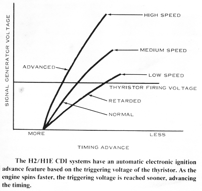
This system also has an automatic timing advance feature. The thyristors (in the
ignition units that conduct the charge in the capacitor to the primary winding
of the high-tension coil) always "turn on" when the voltage from the signal coil
reaches a certain level. As the engine speed rises from idle, the
now-faster-moving magnet in the signal rotor generates a higher voltage in the
signal coil. The voltage in the coil, because it must rise higher in the same
amount of time, rises more quickly. This means that the firing voltage of the
thyristor is reached sooner and the ignition timing is advanced.
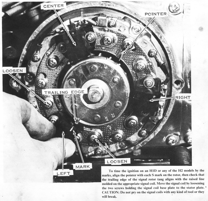
TIMING THE HID/H2 IGNITION SYSTEM MATCHING THE TIMING MARKS
Adjust the ignition timing only after having set the air gap. Turn the
crankshaft until the S mark on the signal rotor nearest the L mark
aligns with the pointer on the stator (located at about 2 o'clock). The trailing
edge of the rotor tang should align with the raised line molded onto the top of
the left cylinder signal coil (located at about 7 o'clock). If it does not
align. loosen the two screws holding the signal coil mounting plate to the
stator, then move the signal coil as required. CAUTION: Do not pry on the
signal coil with any kind of tool. It is very delicate and will break easily.
Move it only with your fingers. When the marks align, tighten the screws and
recheck the alignment. Now rotate the crank till the S mark nearest the
R mark aligns with the pointer and repeat the procedure for the signal
coil at 4 o'clock. Rotate the crank again to align the S mark nearest the
C mark with the pointer, and then repeat the procedure for the top signal
coil.
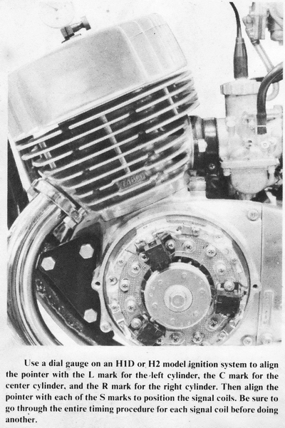
TIMING THE IGNITION SYSTEM WITH A DIAL GAUGE
Remove all spark plugs, then screw a dial gauge adaptor into the left spark plug
hole. leaving the clamp screw loose. Turn the crankshaft back and forth until
TDC is indicated by the needle's reversing direction. Push the dial gauge into
the adaptor until the small pointer indicates 5mm. CAUTION: If the dial gauge
is forced past 5mm, the delicate internal mechanism will be jammed. Tighten
the clamp screw to secure the dial gauge in this position. Turn the crankshaft
back and forth past TDC while rotating the dial bezel so that the needle
registers zero just as it reverses.
Starting with the crankshaft at TDC, slowly turn it clockwise. Count the number
of rotations of the needle and stop when it indicates a piston drop of 3.45mm
(25° BTDC) for the H1D and 3.13mm (23° BTDC) for the H2 models. At this point,
the pointer on the stator plate (located at about 2 o'clock) should align with
the L mark on the edge of the signal rotor. If it does not, bend it
carefully as required. Now turn the crankshaft so that the pointer aligns with
the S mark nearest the L mark. The trailing edge of the signal
rotor tang should now align with the raised line molded onto the signal coil. If
it does not. loosen the two signal coil base plate mounting screws and move the
signal coil as required. CAUTION: Do not pry on the signal coil with any kind
of tool. It is very delicate and will break easily. Move it only with your
fingers. Move the dial gauge to the other two cylinders and repeat the
procedure with the other two signal coils. When the ignition is timed properly,
the air gap must be between 0.020" and 0.031". Replace the spark plugs, spark
plug wires, and ignition cover. Be sure to put the right wire on each of the
spark plugs.
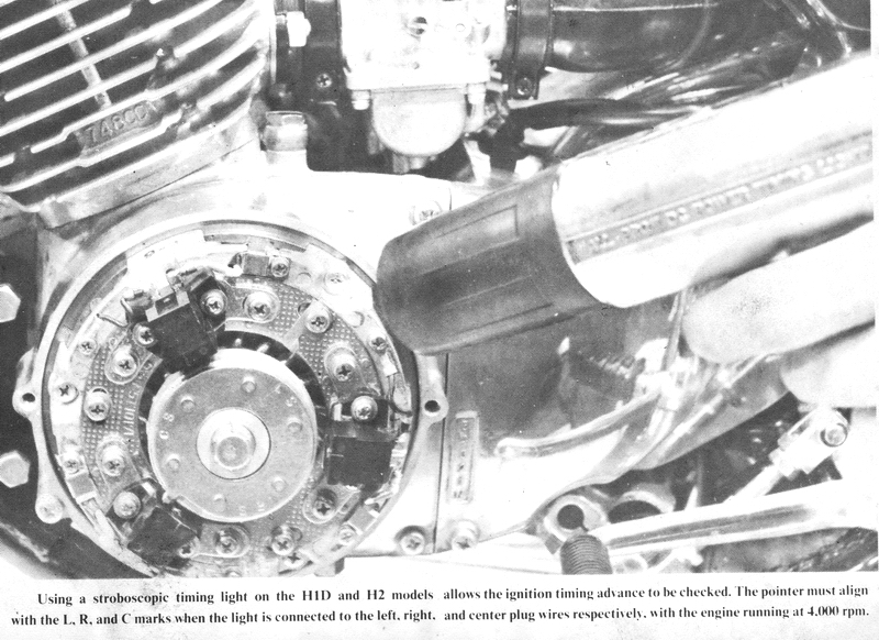
IGNITION TIMING WITH A STROBOSCOPIC TIMING LIGHT
Warm the engine to normal operating temperature. Shut it off, remove the
ignition cover, and attach a stroboscopic timing light to the left cylinder
spark plug wire.
Start the engine and have a helper hold it at 4,000 rpm. The pointer should
align with the L mark. If it does not, loosen the lower left signal coil
base plate mounting screws and change the ignition timing as required. The
center and right cylinders must be timed separately. Move the timing light leads
to each of the other two spark plug wires and check the timing again. The top
signal coil times the center cylinder; the right-hand signal coil. the right
cylinder. When the timing is properly set. remove the timing light, check that
all screws are secure, and replace the ignition cover.
TROUBLESHOOTING THE H1D/H2 IGNITION SYSTEM
As in any ignition system. the most likely part to fail is the spark plug.
Remove the plugs to check them. The electrodes should be burned and rounded
unless they are new. Clean the carbon off the electrodes and the center
insulator. CAUTION: Do not stress the center electrode or insulator, as the
insulator can break. If a plug has a broken or cracked insulator, it must be
replaced. File the electrodes square on the ends with a small file. Set the gap
by bending the outer electrode, only, to 1.0mm (0.040"). This wide a gap is used
because of the extremely high voltage potential of the ignition system.
After cleaning and gapping the spark plugs. check for spark at the plugs by
removing the plugs one by one and laying them on the cylinder head with the
high-tension lead attached. Now kick start the engine. If there is a spark at
the spark plug electrodes, repeat the test with the other two plugs. If all
three plugs spark when the engine is kicked over, check the ignition timing, and
then try to start the engine again. If it still won't run, follow the
instructions in Chapter 1, Troubleshooting, to test the other systems of the
motorcycle. If one or more of the plugs does not have a spark at its electrodes,
pull the plug from the high-tension wire and try to jump a spark from a
screwdriver inserted in the spark plug cap to the cylinder head while kicking
over the engine. If there is a spark now, the spark plugs are faulty and must be
replaced. If there is no spark, the other components of the ignition system must
be checked.
The wiring of this ignition system is very complex. It can easily be hooked
together incorrectly. Be sure that the white wires from the signal coils go to
the right CDI units. Each wire is marked R, C, or L, for Right, Center, or Left
cylinder. The markings on both parts of each white wire must match or they are
hooked up incorrectly. Be sure that the red wires from the units to the
high-tension coils are also properly connected. They are marked R, C, or L, too.
Check that the white wire and the red wire from each ignition unit are marked
with the same letter. If they are not, correct them before proceeding further by
referring to the wiring diagram.
The ignition units can be checked by substituting them for each other, as the
possibility of all three units and the rectifier going bad all at the same time
is extremely remote. Sometimes one bad CDI unit can prevent the others from
sparking too. To test for this, disconnect all three green wires from the
rectifier to the ignition units. Connect one wire at a time and check that
cylinder for spark. If two of the units now work and one doesn't, that one is
bad and must be replaced.
If at least one cylinder has spark while all three ignition units are connected
to the rectifier, the CDI unit(s) for the nonsparking cylinder(s) may not be at
fault. The substitution test must be used, as follows.
First, switch the light green wire for a sparking cylinder and a
nonsparking cylinder. If the bad cylinder now sparks and the good one doesn't,
the ignition rectifier is defective and must be replaced. If the nonsparking and
sparking cylinders stay that way, go on to the second step.
Second, reverse the high-tension leads for a sparking cylinder and a
nonsparking cylinder. Switch the red wires (from the CDI units to the
high-tension coils) between the same two cylinders. Check again for spark while
trying to kick start the engine. If the problem has switched to the good
cylinder. and the nonsparking cylinder now works, the ignition coil for the
nonsparking cylinder is defective and must be replaced. If the locations of
sparking and nonsparking conditions do not change places, go on to the third
step.
Third, reconnect the high-tension leads as they are supposed to be, but
leave the red wires connected as in the second step. Switch the white wires for
the sparking and nonsparking cylinders. If the good cylinder now has no spark,
the CDI unit for the nonsparking cylinder is defective and must be replaced. If
the problem stays with the nonsparking cylinder, then the signal coil for that
cylinder is defective and must be replaced. CAUTION: Once you have located
the defective part, be sure to reconnect the wiring properly. Failure to do so
can cause mechanical damage to the engine when it is run.
To check the low- and high-speed coils in the stator of the alternator, first unplug the three-pronged plug with the blue, green. and white wires. Using an ohmmeter, measure the resistance between the blue and green wires, which should be 5 ohms. If it is less than 5 ohms, the high-speed coil is shorted internally; if it is more, the coil has an open circuit in its winding. In either case, the entire stator unit will have to be replaced. Now check the resistance between the white and green wires, which should be 200 ohms. If it is less than 200 ohms, the low-speed coil is shorted internally; if it is more, the coil has an open circuit in its windings. In either case. the entire stator unit must be replaced.
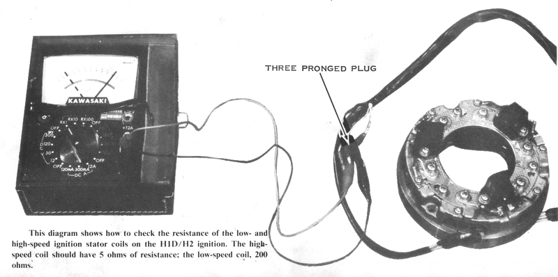
H1E AND H1F MODEL IGNITION SYSTEM
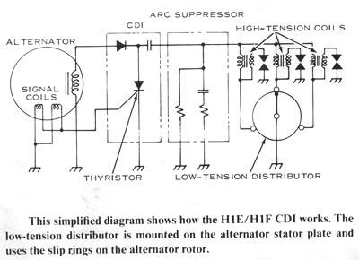
This ignition system is the latest in a long line of CDI systems. It combines
the reliability and high output of the H1D/H2 type of system with the simplicity
of a distributor system. The power for the H1E/H1F ignition system comes from a
special alternator that uses the regular alternator rotor (with its permanent
magnets) and has a single coil on the alternator stator. When the engine is kick
started. the magnets of the spinning rotor induce a high-voltage alternating
current in the winding of the ignition's alternator coil. The current is fed to
the single CDI unit through the orange and brown wires. A diode in the unit
rectifies the alternating current to direct current, which charges the capacitor
in the unit. As the engine turns, the signal rotor (outboard of the alternator
rotor) turns past the two signal coils. The two signal coils are placed in such
a manner that when the signal rotor is positioned with one of its three
projections between the two coils, they will send a small pulse to the CDI unit
via the single white wire. When the pulse gets to the CDI unit. it gates a
thyristor: that is. it "turns on" the thyristor like an electronic switch. The
thyristor now connects the capacitor to the primary windings of the three
high-tension ignition coils.
On the outer face of the alternator rotor is a set of grounded and insulated
slip rings that are contacted by a set of five brushes; two brushes ground
portions of the slip ring arrangement and the others are connected each to the
primary winding of one of the three high-tension coils. The slip rings and
brushes are arranged so that only one high-tension coil will be grounded at any
one time. So, as the thyristor conducts the charge from the CDI capacitor to the
high-tension coils, only one of the coils' primary windings is grounded. The
others are open circuited so they do not conduct. The charge from the capacitor
builds a powerful magnetic field around the core of the grounded high-tension
coil and, as the rising lines of force cut across the secondary winding of the
coil, a very high voltage is induced in it. This voltage fires the spark plug.
The slip ring/brush arrangement used to direct the capacitor's discharge to only
one of the three high-tension coils is called a low-tension distributor because
it operates on the low-voltage side of the high-tension coil. This is why there
must be one high-tension coil for each cylinder in spite of the presence of a
distributor.
There is a second "black box" in this ignition system, which is connected to the
CDI unit by a yellow wire and is grounded. This is the arc suppressor. Its job
is to prevent the brushes from arcing to the slip ring when the capacitor
discharges.
TIMING THE H1E/H1F IGNITION SYSTEM MATCHING THE TIMING MARKS
Adjust the ignition timing only after having set the air gap. Turn the
crankshaft counterclockwise until the second notch on the edge of the alternator
rotor aligns with the pointer (located at 10 o'clock). The trailing edges of two
of the signal rotor tangs should align with the raised lines molded onto the
tops of the signal coils. If the lower signal coil does not align, loosen the
three base plate screws, then rotate the entire base plate as required. Tighten
the base plate screws securely and recheck the alignment. If the upper signal
coil does not align, loosen the signal coil mounting screws, then move the
signal coil as required. CAUTION: Do not pry on the signal coil with any kind
of tool. It is very delicate and will break easily. Move it only with your
fingers. Tighten the screws, then recheck the alignment and the air gaps.
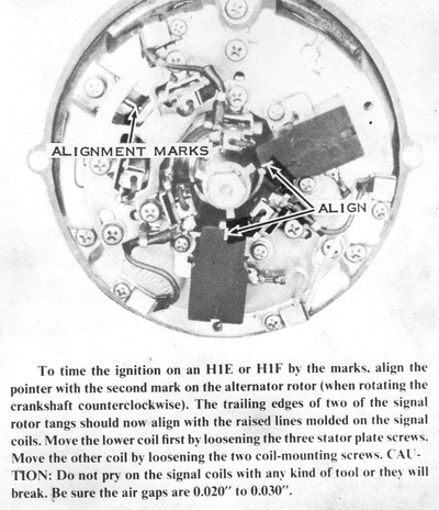
TIMING THE IGNITION WITH A DIAL GAUGE
Remove all spark plugs, then screw a dial gauge adaptor into the left cylinder
spark plug hole, leaving the clamp screw loose. Turn the crankshaft with a
wrench until TDC is indicated by the needle's reversing direction. Push the dial
gauge into the adaptor until the small pointer registers 5mm. CAUTION: If the
dial gauge is forced past 5mm, the delicate internal mechanism will be jammed.
Tighten the clamp screw to hold the dial gauge in this position. Turn the
crankshaft back and forth past TDC while turning the dial bezel so that the
needle registers zero just as it reverses.
Starting with the crankshaft at TDC, slowly rotate it clockwise until the dial
gauge indicates a piston drop of 2.94mm, which is exactly 23° BTDC. If the
pointer (located at 10 o'clock) does not align with the mark on the alternator
rotor, loosen the screw and move the pointer as required. Now turn the
crankshaft counterclockwise until the pointer aligns with the second mark on the
alternator rotor. At this point. the trailing edges of one signal rotor tang
should align with the raised line molded onto the signal coil, located at 6
o'clock. If it does not, loosen the three stator plate screws and move the
entire stator plate as required. After tightening the screws. check that the
trailing edge of the right signal rotor tang aligns with the mark on the other
signal coil. If it does not, loosen the two signal coil mounting screws and move
it as required. CAUTION: Do not pry on the signal coil with any kind of tool.
It is very delicate and will break easily. Move it only with your fingers.
Tighten the screws carefully, then check the air gap, which must be 0.020" to
0.030". Replace the spark plugs. spark plug wires, and ignition cover. Be sure
to put the right wires on the spark plugs.
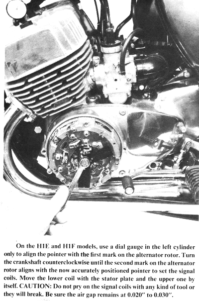
IGNITION TIMING WITH A STROBOSCOPIC TIMING LIGHT
Warm the engine to normal operating temperature. Shut it off, remove the
ignition cover, and attach a stroboscopic timing light to the left cylinder
spark plug wire.
Start the engine and have a helper hold it at 4,000 rpm. The pointer should
align with the notch on the alternator rotor on the H1E and H1F models. If it
does not, loosen the stator plate screws and change the ignition timing as
required. The other two cylinders are now timed properly as well. When the
timing is properly set, remove the timing light, check that all screws are
secure, and replace the ignition cover.
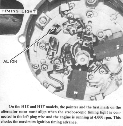
TROUBLESHOOTING THE H1E/H1F IGNITION SYSTEM
If the engine will not run, you must first check for spark at the spark plugs.
To do this, remove the plugs one at a time, lay them on the cylinder head with
their high-tension leads attached, and try to kick start the engine. There
should be a spark across the electrodes of the spark plugs. If there is none,
pull the plug off the high-tension lead and put a screwdriver into the spark
plug cap, holding it near the cylinder head. Now kick start the engine. If a
1/16" spark jumps from the screwdriver blade to the head, the spark plug is
defective.
Clean the carbon off the electrodes and out from around the center electrode
insulator. CAUTION: Do not stress the center electrode (or its insulator) or
the insulator will break. Inspect the insulator for cracks. Discard any
plugs with a cracked or broken insulator. File the electrodes square and gap the
plugs to 1.0mm (0.040"). If they now spark properly, check the timing and then
the other systems of the engine as described in Chapter 1, Troubleshooting.
After the spark plug, the next most likely trouble spot is the low-tension
distributor. To check it, unplug the three black wires from the high-tension
coils to the brushes. Use alligator clips or something similar to ground all
three coils. Now try to kick start the engine. NOTE: The engine will operate
almost as well with all three coils grounded at once as with the distributor
working, but all three coils fire all three plugs at the same time. One cylinder
is ready to fire and does; one cylinder is near the end of the exhaust stroke
and cannot fire; the third is halfway through the transfer portion of the cycle
and cannot fire either. CAUTION: Do not run the engine any longer than
necessary with the distributor bypassed in this manner, because it puts an extra
strain on the rest of the system. One hundred miles is a safe upper limit.
If the engine runs, the distributor is at fault, and its components must be
checked individually.
To check the distributor further, remove the alternator cover on the left end of
the engine. Take out the screw holding each of the inner brushes to the stator
plate. These brushes are connected to the high-tension coils. Make an alignment
mark on the stator plate and on the stator (so that you can put the stator plate
back in the position for proper ignition timing), and then remove the stator
plate. Clean the surface of the slip rings with electrical contact cleaner and a
soft cloth. Clean any foreign matter out of the slits that separate the parts of
the inner slip ring.
Now measure the resistance between the two segments of the inner slip ring, and then from between the independent segment of the inner slip ring and the signal rotor (or the center of the alternator rotor). The resistance should be infinite in both cases. If it is anything less, the slip ring plate is defective and the entire alternator rotor must be replaced. If the surface of the slip rings is pitted or scratched. you may be able to salvage it by polishing it with # 600 or finer emery paper. The slip ring surface must be very smooth or it will cause accelerated brush wear.
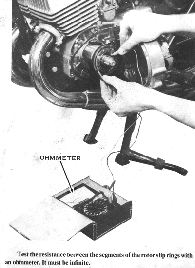
Brush wear is easily checked by looking for the red line scribed around the
brush, which marks the service limit. Brushes generally last for more than
20,000 miles unless the slip rings are dirty, pitted. or scratched. Reassemble
the stator plate and remount the alternator cover.
A badly pitted slip ring and burned brushes can mean one of two things: either
the arc suppressor is defective or the engine is not well grounded. Of these two
conditions. it is far more likely that a poorly grounded engine has caused the
problem. This model has a rubber-mounted engine (for less vibration) and a
separate ground wire from the top screw of the chain case cover to the upper
rear engine mount bolt. Check to see that it is in good condition. Use an
ohmmeter to check the resistance between the frame and the engine, which should
be zero. If it is any higher, the ground wire is at fault. Disconnect the ground
wire and clean the contact areas on both ends of the wire, on the engine, and on
the frame with an oilless solvent such as trichloroethylene or an electrical
contact cleaner. Install the wire and retest the resistance. If it is still
greater than zero, replace the wire and try again.
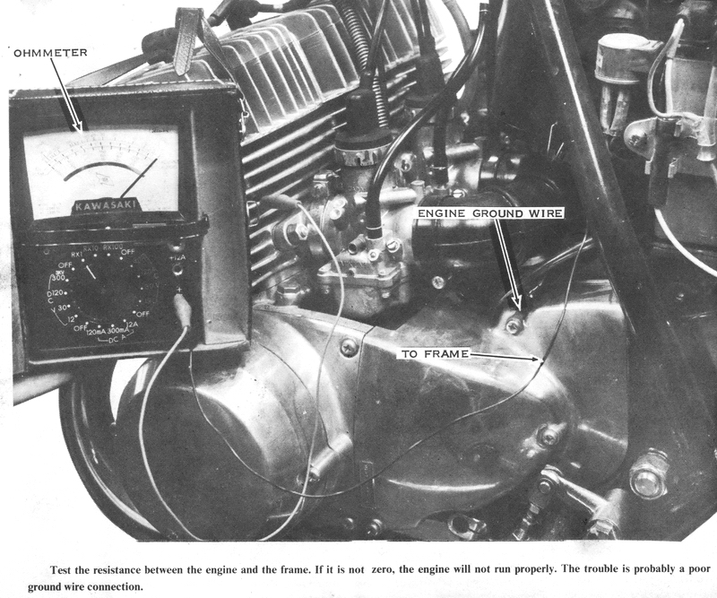
To test the arc suppressor, first remove it from the motorcycle. Measure the
resistance between its yellow and black wires, which should be 300 ohms. If it
is more or less than this, the arc suppressor is defective and must be replaced.
NOTE: The engine may be run briefly without the arc suppressor, but not more
than one hundred miles.
The signal generator coils should be checked next. Remove the alternator cover,
then disconnect the ground terminal screw (black wire) for each signal coil.
With an ohmmeter, test the resistance between the ground wire and the white wire
for both signal coils, which should be 260 ohms. If it is not, the signal coil
is defective and must be replaced.
If only one or two spark plugs will not spark, the trouble can be a defective high-tension coil. To test the high-tension coils, first determine that the distributor is in good condition, as described previously, and then disconnect all wires to the nonsparking coil. With an ohmmeter, check the resistance between the white wire and the black wire that runs from the coil to the distributor. The meter should read approximately one ohm. If it is higher than 10 ohms or less than 1/2 ohm. the coil is defective and must be replaced. Now check the resistance between the high-tension lead and the black wire to the distributor and between the white wire and ground. In both cases the resistance should be infinite. If it is any less. the coil is internally shorted and must be replaced. NOTE: This high-tension coil is different from any other motorcycle or automobile high-tension coil because the primary and secondary windings are separately grounded. CAUTION: Do not use anything but a genuine Kawasaki replacement part, or damage to the distributor will result.
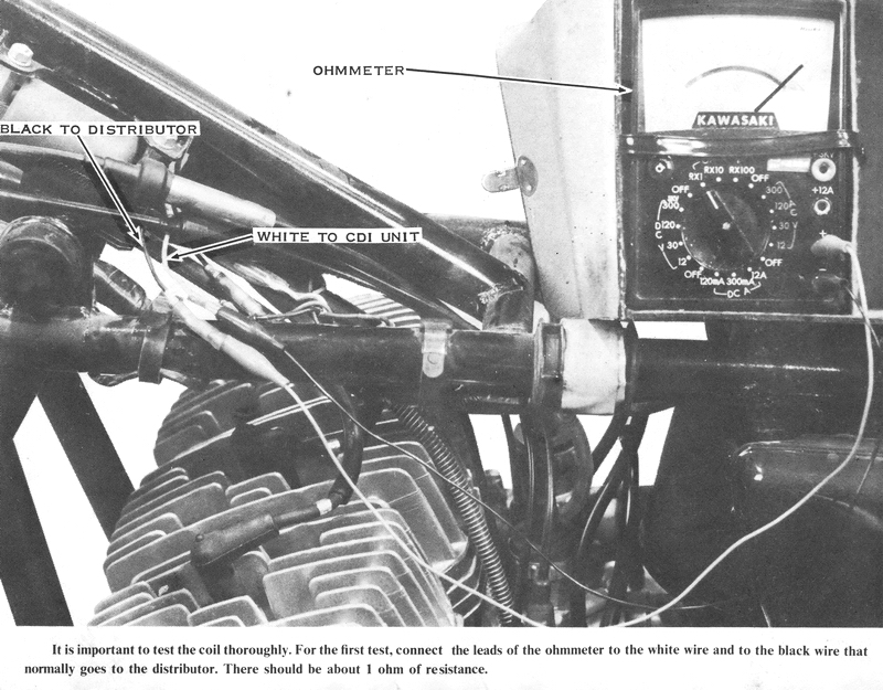
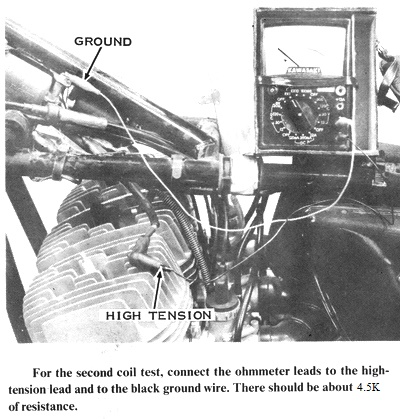
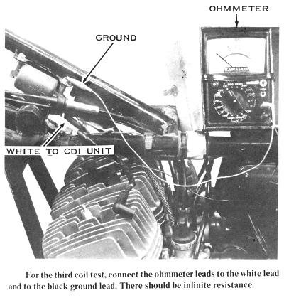
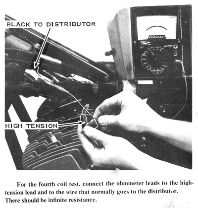
Finally, test the special alternator coil on the stator. To do
this, raise the seat and unplug the two-prong rubber connector with the brown
and orange wires. With an ohmmeter, test the resistance between the brown and
orange wires to the alternator, which should be 115 ohms. If it is not, the coil
is defective and the entire stator assembly must be replaced.

There is no way to test the CDI unit without special testers that are not
generally available. If the system passes all the previously described tests and
still won't spark any of the plugs, by process of elimination the CDI unit is
defective and must be replaced.
LIGHTING SYSTEM AND WARNING DEVICES
All Kawasaki triples have essentially the same lighting system with only minor
differences in switch type and placement. The lighting system is run directly by
the battery. The ignition switch controls the power available to the lights and
horn even on those models that have separate light switches (besides the Hi-Lo
beam switch for the headlight). The headlights all are dual-filament,
sealed-beam types (except for 1969 and 1970 H1's which were available with
bulb-type headlights). The taillights all use the same dual-filament bulb for
both the taillight and brake light. The turn signals differ slightly from model
to model (1972 models and later) but all use the same bulb and flasher unit.
HEADLIGHT
All model headlights are dual-filament types for high and low beams. The beam
switch is in the left-hand switch case. On 1975 models the beam switch is pushed
up for high beam and down for low. On all previous models it was the opposite.
The headlight switch is incorporated into the ignition switch on H1's from 1969
through 1971. All models from 1972 onward have a separate headlight switch. On
the 1972 H1B, H1C, and H2, the headlight switch is in the left-hand switch case.
On all models from 1973 onward, the headlight switch is in the right-hand switch
case. On any model. the headlight will work only with the ignition switch turned
on.
ADJUSTING THE HEADLIGHT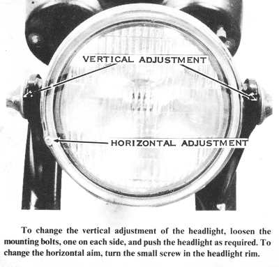
Headlight aiming laws vary from state to state, but generally speaking the low
beam should be aimed slightly to the right, and should drop about 2" in 25 feet
to avoid dazzling oncoming drivers' eyes. The vertical adjustment of the
headlight is extremely simple. Loosen the two large mounting bolts, one on
either side of the headlight shell, and then push the light up or down as needed
while sitting on the motorcycle. To make this more accurate, measure the
distance from the center of your motorcycle's headlight to the ground, and then
make a cross-mark on a wall at that height. Sit on your motorcycle at night, 25
feet from the wall on level ground, and adjust the headlight so that the center
of the bright spot of the light is 2" below the cross-mark. Tighten the
headlight mounting bolts.
To adjust the side-to-side aim. turn the small screw on the left side of the
headlight rim when viewed from the front. Turn the screw clockwise to aim the
headlight more to the rider's left and counterclockwise to aim the headlight
more to the rider's right. Now sit on your motorcycle at the same place, 25 feet
from the wall with the front wheel aimed directly at the cross-mark on the wall.
The center of the bright spot of the headlight should be about one inch to the
right of the cross-mark on the wall. NOTE: Check your local law enforcement
agency for exact headlight-aiming specifications.
TAILLIGHT
The headlight switch also activates the taillight on all models. One filament of
the bulb is used for the taillight, the other for the brake light. The bulb used
is a number 1034 or 1157 (either will work in any model) which is used in the
taillights of almost all American automobiles. It can be purchased at any
service station. The brake light has two independent switches; one is operated
via a spring from the rear brake pedal; the other is a hydraulic switch in the
front brake hydraulic system on disc-brake models, and a built-in switch in the
cable of drum-brake models. The taillight and brake light will work only with
the ignition switch turned on.
ADJUSTING THE BRAKE LIGHT SWITCH
The front brake light is not adjustable on any model, but the rear brake light
switch is, and the adjustment is the same on all models. After adjusting the
rear brake and brake pedal height (as described in Chapter 6, Frame and Running
Gear Service), you will have to adjust the rear brake light switch so that the
brake light is activated when the pedal is depressed 3/4". Loosen the adjuster
nuts on the body of the switch. If the pedal must be depressed more than 3/4" to
turn on the light, tighten the upper adjuster nut to move the switch upward. If
the lamp lights before the pedal is moved far enough, tighten the lower adjuster
nut to move the switch down. Tighten both nuts, then test the adjustment.
CAUTION: Do not overtighten the brake light switch adjuster nuts or you will
break the body of the switch.
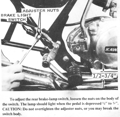
TURN SIGNALS
The turn signals on all models have a switch in the left-hand switch case. It
has three positions: center for off, left to signal a left turn, and right for a
right turn. The switch must be manually returned to the center position after a
turn has been completed. All models use the same flasher unit and the same turn
signal bulbs, though the units and the lenses are different on different models.
The only models that did not have stock turn signals were the 1969 to 1971 H1
and H1A. Later model turn signals can be modified to fit; only the mounting is a
problem. (The switch and wiring are already there. The alternator and the
battery are more than capable of supporting the extra load.) The turn signal
units from the 1972 H2 or S2 are the most easily adapted to the earlier H1's.
and the increased safety makes the work and expense worthwhile.
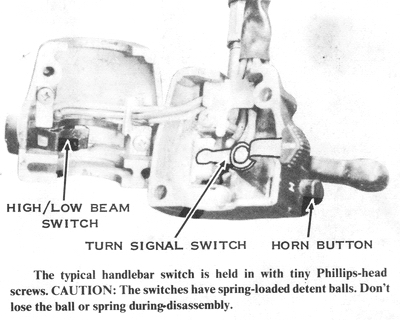
HORN
All models are equipped with a horn mounted underneath the steering stem on the
frame. The horn button is in the left-hand switch case. The horn works only with
the ignition switch turned on. The horn is not adjustable for either tone or
volume.
TROUBLESHOOTING THE LIGHTING SYSTEM BULBS
The most common problem in any lighting system is burned-out bulbs. If a lamp
won't light, check the bulb first. Remember that the headlight and taillight
bulbs must have two filaments each. If there is only one left, then one function
of the light will not be fulfilled. CAUTION: When replacing the taillight and
turn signal lenses, do not overtighten the screws. The plastic lenses will
break.
SWITCHES
If a bulb is not burned out, check the wiring and the switches for continuity.
To do this, use an ohmmeter. First disconnect the battery leads. Now measure the
resistance from the center contact of the socket of the bulb that won't light to
the nearest connector on the wire that goes to the switch. NOTE: Check the
wiring diagram at the end of this chapter for the color of the wire. The
resistance along the length of the wire should be zero. If it is higher, the
wire must be replaced. Test the resistance of the switch by connecting the
ohmmeter to the incoming and outgoing wires of the switch. Again, the wiring
diagram will tell you what color wires to look for. There should not be any
resistance here either. If there is, there may be corrosion in the switch. To
clean the switch, remove the switch case screws, then split the switch case off
the handlebars. Before disassembling the switch itself, try cleaning it with an
electrical contact cleaner. Squirt the cleaner into the contacts of the switch
and work the switch back and forth rapidly for 10 or 15 seconds. Now try the
resistance test again. If the problem has disappeared, assemble the switch case
onto the handlebars; if it hasn't, you must disassemble the switch for cleaning.
To disassemble a handlebar switch, remove the tiny screw holding the switch
parts to the inside of the case. CAUTION: Most of the switches have
spring-and-ball detents. Do not lose the ball, as the spring may suddenly throw
it out of the switch case. Carefully lift out the switch contact plates.
Clean the copper contact spots with trichloroethylene or other oilless solvent
and a soft cloth. When the contacts are clean, reassemble the switch. Be careful
to include all the springs and other small parts that came out. If parts of a
switch are broken, the entire switch case must be replaced, as parts for the
switches are not available separately.
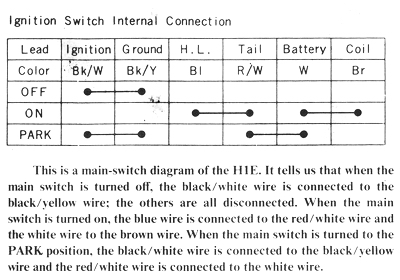
MAIN SWITCH
To test the resistance across the main switch, first decide which wires are
electrically connected in the different switch positions. Each wiring diagram
has a block diagram of the switch positions. Across the top of the diagram are
the wires listed by their function and color (at the switch). Down the side of
the diagram are the switch positions. To the right of each position are black
bars connecting heavy dots under different wires. In that switch position, the
wires that are dotted are connected the same as the dots. Some wires are the
same from model to model. The main "hot" wire from the battery to the main
switch is always white. With the switch in the ON position, the white wire will
be connected with the brown wire. If there is any resistance at all across any
connected wires, with the switch in the ON, DAYTIME, or NIGHTTIME positions, the
switch must be replaced.
REAR BRAKE LAMP SWITCH
The rear brake lamp switch is located on the right side of the motorcycle on the
vertical frame tube above the footpeg. If the brake lamp does not light when the
brake pedal is depressed, check the switch by pulling down on the spring
connecting the switch to the brake pedal. If the lamp now lights, the switch
needs to be adjusted as described earlier in this chapter. If the brake lamp
still doesn't light, disconnect the wires to the switch and connect them with a
short piece of wire. If the brake lamp still doesn't light, the problem is a
burned-out bulb or an open circuit in the wiring to the brake lamp. Check with
an ohmmeter all the connectors and the wires going to the lamp for continuity.
If the lamp lights, the switch is defective and must be replaced. NOTE:
Sometimes a broken brake lamp switch can cause the fuse to blow out. This
happens when the switch adjustment nuts are over-tightened, which breaks the
switch body, causing an internal short circuit.
FRONT BRAKE LAMP SWITCH
The front brake lamp switch is located either on the front brake cable (on drum
brake models) or in the hydraulic system on the lower triple clamp of the forks
(on disc brake models). Neither is adjustable. but either can fail. If the brake
lamp does not light when the brake lever is squeezed, pull the two wires off the
switch. Use a short length of wire to connect the two wires. The brake lamp
should now light. If it doesn't, the problem is either a burned-out bulb or an
open circuit in the wiring. Check with an ohmmeter all connectors and the wires
going to the brake lamp for continuity. If the brake lamp does light, the front
brake lamp switch is defective and must be replaced. On drum brake models, this
means you must replace the entire front brake cable. On disc brake models, you
must bleed the hydraulic system after replacing the switch. (For instructions on
bleeding the hydraulic system, see Chapter 6. Frame and Running Gear Service.)
TURN SIGNALS
The turn signal circuits are simple and easy to troubleshoot if you know how to
interpret the symptoms of failure. If the indicator lamp lights but does not
blink when the signals are activated, then one of the bulbs is burned out or one
of the signal lamp housings is not grounded. To check for a good ground, measure
with an ohmmeter the resistance between the wall of the bulb socket and the
frame. The resistance should be zero. Any higher reading means that the ground
connection is bad. To repair it, clean the areas where the black ground wires
attach to the frame. If there are no ground wires, clean the area where the turn
signal stalk attaches to the frame.
If the turn signals will not light at all, check the switch and the flasher
unit. To test the switch, disconnect the wires to the switch inside the
headlight shell. Use an ohmmeter to test the resistance between the gray wire
and the brown wire with the switch in the right-turn position. Then test the
resistance between the green wire and the brown wire with the switch in the
left-turn position. The resistance should be zero in both cases. If it is any
greater in either or both positions, the switch contacts are dirty. To clean the
switch contacts, first remove the two screws holding the switch case to the
handlebars. Split the case halves. In one half, the switch handle is pivoted on
a small Phillips-head screw. Remove the screw and then lift out the switch
handle. The switch block is held in by the wiring. Pull up the wiring to remove
the switch block. Spread the sides of the block to disassemble it. CAUTION:
The detent mechanism is a spring-loaded ball, which will fly out when the block
is disassembled. The spring and ball are not available separately.
Clean the brass contact surfaces with trlchloroethylene or an electrical contact
cleaner and a soft cloth. When the contacts are clean, reassemble the switch.
then retest its resistance as described previously.
If the indicator lamp on the instrument panel (or on the speedometer face) will
not light, remove it and check the bulb. If the bulb's filament is in good
condition, the socket or the wiring is faulty. Neither wire to the indicator
lamp is a ground wire. The gray wire goes to the right-turn signal circuit and
the green wire to the left-turn signal circuit. Check that these wires go where
they should and that neither is shorted to ground. Check the continuity from the
wall of the indicator lamp socket through the two wires. The resistance should
be zero through one wire and infinite through the other. Check the center
contact of the socket as well. The resistance readings should be opposite the
readings taken on the wall of the socket. Finally, check to be sure the wires
are all connected properly according to the color codes in the wiring diagram at
the end of this chapter.
The flasher unit is very reliable. but if it does become defective, the whole
system (both left-turn and right-turn circuits) will share the problem. If both
the front and rear lamps light but do not flash, the flasher unit is defective
and must be replaced. NOTE: The battery must put out at least 12 volts to
make these tests valid. If none of the signal lamps light, bypass the
flasher with a short piece of wire. If they light now, the flasher is defective
and must be replaced. However, if they still do not light, measure the battery
voltage, and then check the main fuse, main switch, and turn signal switch and
wiring for open circuits.
MAIN FUSE
The main fuse is located behind the left side-cover under the seat on all
models. If the fuse blows, it is because of an electrical overload caused by a
short circuit.
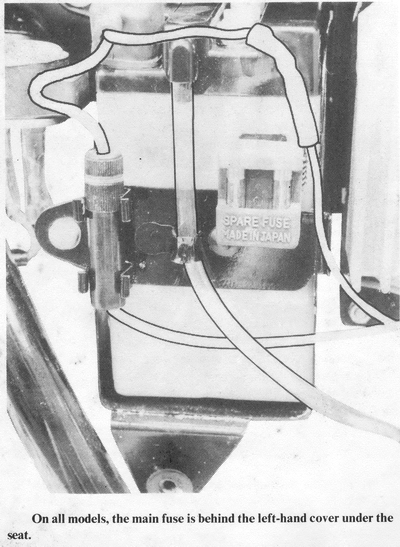
When the fuse blows. think back to what happened immediately before the fuse
blew. On many models. the engine will stop when the fuse blows. but not on the
H1D, H1E, H1F, and H2 models, because they have a magneto-powered ignition
system. If the fuse blows just after the turn signals are switched on, then one
of the turn signal wires is short-circuited to ground and must be repaired. If
the fuse blows as the headlight is turned on, the headlight or taillight
circuits must be short-circuited to ground. If the fuse blows as the brake is
applied, the short is in the brake light circuit. This kind of logic can often
tell you where the problem is even before you start looking for it.
If the problem is not obvious, start from the battery with an ohmmeter and check
the resistance between the "hot" wires (red, white, brown, green, or gray) and
the frame. CAUTION: Be sure to disconnect the battery during these tests or
the ohmmeter will be damaged. As long as the resistance between the hot wire
and the frame is zero, you have not isolated the problem. As an example, the
first wire to check is the wire to the fuse from the positive terminal of the
battery. Replace the fuse. then hold one probe of the meter against the frame
and the other against the end of the wire that is normally connected to the
positive terminal of the battery. Check the resistance before turning on the
main switch. If it is zero. the short is between the battery and the main
switch. If it is infinite. turn on the main switch. The resistance will now drop
to zero. indicating that the short is beyond the main switch somewhere.
Check the wiring diagram to see what color the wires are that are connected to
the white battery wire when the main switch is turned on. These are the wires to
check next. Disconnect them from the main switch and measure the resistance of
each one to ground. The one with zero resistance has the short circuit in it.
Now check the wiring diagram again to see where the problem wire goes.
Disconnect each branching wire from the problem wire. Proceed this way until you
find the last wire that exhibits the problem which is the wire with the short
circuit. NOTE: Remember to disconnect each wire as you test it to be sure you
are checking a smaller piece of the total system each time.