Setting Points Timing
To properly set timing on a points system a dial gauge and detection device are needed. The detection device can be a meter, continuity tester, light bulb or AM radio. If an ohmmeter or continuity tester is used there is no need for battery power. Other methods require battery power with the ignition turned on.
Points should be dressed and cleaned with contact cleaner or rubbing alcohol. New points sets are often coated with a preservative to prevent corrosion. Contact surfaces must be clean and void of oils.
Changes to point gap setting will change timing. For this reason, point gap must be set as accurately as possible to the mid-spec before attempting to set timing. Removing all sparkplugs will allow easy rotation of the crankshaft.
S Series Timing:
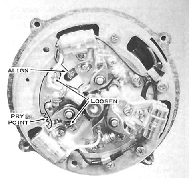
The points on the S series are independently adjustable on each cylinder for timing adjustment. Radial movement will set timing where movement toward or from the crank is to set point gap. Each cylinder must be set.
Insert dial gauge in plug hole and find TDC.
Set dial marker for "zero" or make note of reading.
Rotate crankshaft CCW thru TDC to insure repeatability of TDC point mark on
gauge.
Rotate crankshaft CW by the amount specified in timing
spec (0.102" or 2.60mm).
This is the point where the points set should just open when crank is turned
CCW.
It should also be the point where the timing mark is visible and aligned thru
the window in the stator plate.
If the marks are aligned (my experience is that they will be) then the marks can
be used rather than the dial indicator.
If the marks do not align then doublecheck all previous procedures.
Connect your detection device to the points set. If power is required, turn the key on.
Loosen screws noted in image above.
As the crank is rotated CCW at the alignment mark match
or dial gauge setting the detection device used should activate.
Adjust point set via pry point until this is achieved.... always when turning
CCW thru that point.
Tighten points set and move on to next cylinder and repeat procedure.
H1B Timing:
Spec timing of the H1B is 20deg BTDC. This was a change in a CYA procedure. The H1B will NOT have desirable performance if set per spec. I would recommend about 24 deg (0.126" or 3.20mm BTDC) for best performance.
Timing of the H1B is accomplished by rotating the stator plate where all three cylinders are changed at the same time.
Insert dial gauge in left cylinder plug hole and find TDC.
Set dial marker for "zero" or make note of reading.
Rotate crankshaft CCW thru TDC to insure repeatability of TDC point mark on
gauge.
Rotate crankshaft CW by the amount specified in timing
spec (0.126" or 3.20mm BTDC).
This is the point where the points set should just open when crank is turned
CCW.
Make note of this dial gauge set point.
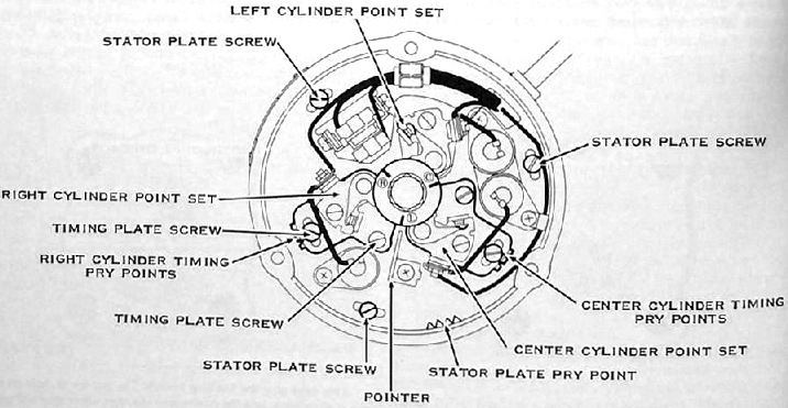
Loosen stator plate screws noted in image above.
As the crank is rotated CCW at the exact dial gauge
setting the detection device used should activate.
Adjust stator plate via pry point until this is achieved.... always when turning
CCW thru that point.
Sometimes the stator plate cannot be rotated far enough
to achieve this.
If this is the case, the slots must be elongated in the plate to provide
additional adjustment range or the point gap must be adjusted until point
opening is achieved at that point.
Tighten stator plate.
Once points set is opening at the proper dial gauge
setting, bend the pointer to match the alignment mark on the end of the
crankshaft.
In theory, you can now use the matching pointer alignment to set the other
cylinders. However, it is better and more accurate to continue with the
dial gauge on the next cylinder(s).
If the next points set does not open at proper dial gauge set point, loosen timing plate screw on individual points, adjust point gap via points set pry point, retighten screw.