SOLID STATE VOLTAGE REGULATOR
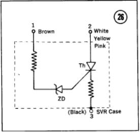 Models KH400, KH250, and S series are equipped
with a solid state voltage regulator (SVR). This unit consists of a zener diode
(ZD), a thyristor (Th), and two resistors, as shown in Figure 26.
Models KH400, KH250, and S series are equipped
with a solid state voltage regulator (SVR). This unit consists of a zener diode
(ZD), a thyristor (Th), and two resistors, as shown in Figure 26.
KH250 and S Series
Troubleshooting
If a malfunction of the solid state voltage regulator is suspected, it
may be checked by the following tests. However, bear in mind that if the
battery is low, the regulator will not work properly even though it may be in
good condition. Therefore, be sure that the battery is in good condition and
at or near full charge before attempting to trouble shooting a suspected
malfunction.
 1. Measure
resistance between the brown wire and the case. Resistance must be greater than
1,000 ohms.
1. Measure
resistance between the brown wire and the case. Resistance must be greater than
1,000 ohms.
2. Measure resistance in both
directions between terminals 2 and 3. Resistance should be essentially
infinite in both directions.
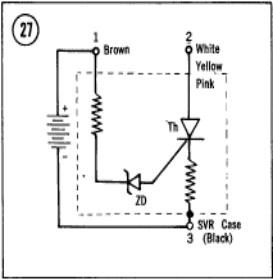
3. Connect the motorcycle
battery to the regulator as shown in Figure 27. Be careful to observe
proper polarity. No current should flow in the circuit between terminals 1 and
3. Measure resistance between terminals 2 and 3. Resistance should be essentially
infinite.
4. Connect an additional 4 to 6
volt battery in series with the first battery to make a total of over 16 volts
across terminals 1 and 3. If current does not flow, either the zener diode or
the first thyristor is defective.
5. Replace the regulator if it fails any of the
foregoing checks. If its condition is still doubtful, check it by trial
replacement with a known good unit.
KH400 Troubleshooting
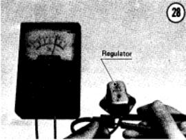
1. Check the
resistance between the black and yellow/green leads (Figure 28). Resistance should be between 1,000-1,200 ohms.
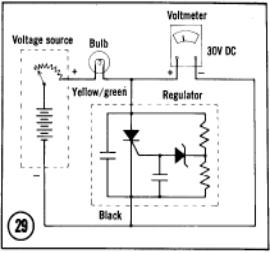
2. Connect
the circuit shown in Figure 29 using
a suitable power supply. Set the voltmeter to the 30V DC range. Turn on the
power supply; the light should be off. Gradually
increase the voltage from 8 to 14 volts; if the regulator is good, the bulb
will light between 10-12 volts.
3. Replace
the voltage regulator if it fails either of these tests. If its condition is
still doubtful, check it by trial replacement with a known good one.
 Handling
Precautions
Handling
Precautions
Certain precautions must be observed when you
handle or service the solid state regulator. Failure to observe these may
result in damage to the unit.
1. Be sure that the mounting screws are tight.
2. Always be sure that the main switch is off before
connecting or disconnecting the unit.
3. Be sure that the unit is mounted securely.
4. Be sure that the wires are connected properly.
Improper wiring will result in damage to the battery and regulator.
5. The battery must be charged to near full capacity
for the regulator to work properly. If the battery is very low, charge it
before installation.
ELECTROMAGNETIC VOLTAGE REGULATOR—H1
Operation
 Some alternators use separately excited field
windings. Such alternators require a more complex regulator. As engine speed
increases, alternator output tends to increase. It is possible, however, to
control alternator output by controlling its field current, which is used for
excitation.
Some alternators use separately excited field
windings. Such alternators require a more complex regulator. As engine speed
increases, alternator output tends to increase. It is possible, however, to
control alternator output by controlling its field current, which is used for
excitation.
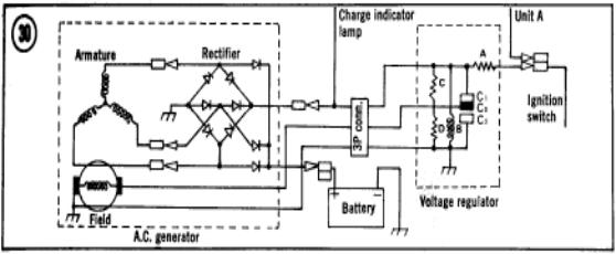
Figure
30 illustrates the situation
at low engine speeds. The rectified alternator output is applied to coil B.
However, since the output is low, the magnetic field developed by coil B is too
low to open contacts C and C0. Under these conditions, field current
is supplied by the battery through the ignition switch, and is at its maximum
value.
As alternator output voltage tends to increase,
coil B develops more magnetic force, which breaks contacts C and C0.
Field current is then supplied from the alternator output through resistor C.
Resistor C limits the field current, and thereby reduces alternator output so
that contacts C, and C0 again close, repeating the cycle.
At high engine speeds and light electrical
loads, the action of the upper and center contacts is insufficient to control
alternator output. As output voltage continues to rise, coil B pulls the
movable contact C0 down to the lower contact C2. Under this condition
the field is grounded, and alternator output drops to zero. As it drops, the
movable and lower contacts separate, and the cycle repeats.
Regulator Testing
The most common causes of voltage regulator
trouble are open wires or short circuits. To check the regulator, proceed as
follows.
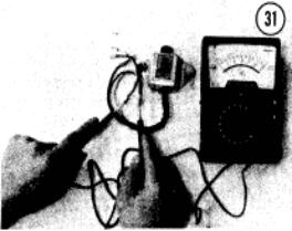
1. Remove the regulator.
2. Measure resistance between the brown and black
leads (Figure 31). Resistance should be approximately 55 ohms.
3. Connect a
voltmeter across the battery terminals. Reconnect the regulator.
4. Start the
engine and run it at 5,000 rpm. If the measured voltage is 14.5 plus or minus 0.5, the regulator is OK.