Alternator
An alternator is a form of
electrical generator in which a magnetized field called a rotor revolves
within a set of stationary coils called a stator. As the rotor revolves,
alternating current is induced in the stator. The current is then rectified
and used to operate the electrical accessories on the motorcycle and for
charging the battery. The rotor may be either permanently magnetized, or
magnetized by a separate winding in the rotor. Kawasaki machines use both
types.
Alternators with permanently
magnetized rotors are controlled by a solid state regulator. Alternators with
externally excited field windings require a regulator similar to that in an
automobile. Rotors on some models are permanently magnetized; others require
separate excitation.
If alternator or
regulator problems are suspected, as in the case of a chronically undercharged
battery or dim headlights, first check the alternator output voltage:
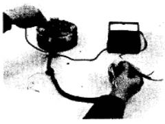
1. Connect a 0-20 DC
voltmeter across the battery terminals. Be sure that you connect the positive
voltmeter lead to the positive battery terminal, and the negative voltmeter
lead to the negative battery terminal.
2.Start
the engine and run it at 5,000 rpm. If the voltmeter indicates 14 to 15 volts,
you may assume that the alternator and regulator are OK.
3.If
the voltmeter does not indicate 14 to 15 volts, further checking will be
required. Trouble may lie in the alternator, regulator, or wiring.
Figure 19B
 KH250, KH400, and
S Series (Without CDI) Alternator Troubleshooting
KH250, KH400, and
S Series (Without CDI) Alternator Troubleshooting
1. There are 3 leads from the alternator. Check for
continuity between the following leads, as shown in Figure 19A.
a. Pink to
yellow
b. Pink to
white
c. Yellow to
white
2.Set
the ohmmeter to its highest range. Connect one lead to any stator wire, and
the other to the alternator housing (Figure 19B). The meter should indicate infinite
resistance.
3.Replace
the stator if the unit fails either of the preceding tests.
KH400 Alternator (with CDI) Troubleshooting
1. There are 3 leads from the alternator to the voltage regulator.
2. Set the ohmmeter to the
R x 1 range. Measure the resistance between the 2 yellow leads; it should be 0.45-0.7 ohms. If the
reading is less, the coils are probably shorted. A higher reading or no reading
at all indicates the coils are open.
3. Set the ohmmeter to the highest
range. Connect one lead to a yellow lead and one to the chassis (frame,
engine, etc.); repeat for the other yellow lead. The meter should indicate infinity.
If there is any meter reading, it indicates a short.
4. If the windings indicate normal
resistance, but voltage and current tests indicate that the alternator is
defective, then the magnets in the rotor are probably weak and must be
replaced.
5. Replace the stator if the unit fails
any of the preceding tests.
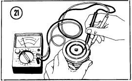
KH500 and H1
Alternator Troubleshooting
1. Measure field winding resistance
between the slip rings, as shown in Figure 21. If the resistance is not
3.5 to 5.5 ohms, replace the rotor.
 2. Measure insulation resistance of the field winding.
Set the ohmmeter to its highest range, then measure resistance between either
slip ring and the rotor shaft. Insulation resistance must be essentially
infinite.
2. Measure insulation resistance of the field winding.
Set the ohmmeter to its highest range, then measure resistance between either
slip ring and the rotor shaft. Insulation resistance must be essentially
infinite.
3. Inspect the brushes. Replace them if they are worn to 3/8 inch (9.3 millimeters). Standard length for new
brushes is 9/16 inch (14 millimeters).
4.
Check for continuity between each pair of yellow wires coming from the
alternator stator.
5. Set the ohmmeter to its
highest range, then measure insulation resistance between the stator housing
and the three yellow leads. Insulation resistance must be essentially
infinite.
H2 Alternator Troubleshooting
1.
Measure resistance between both yellow leads. Resistance should be
approximately 0.4 ohm.
2.
With the ohmmeter set to its highest range, measure insulation resistance
between either yellow lead and ground. Insulation resistance must be essentially
infinite.
3.
Measure resistance between the blue and the green leads. Resistance should be
approximate1y 5 ohms.
4.
Measure resistance between the black lead and each white lead. Resistance
should be approximately 200 ohms.
5. Measure
resistance between the white and green leads. Resistance should be approximately
200 ohms.