Zeeltronic PCDI-30 Installation
and Setup
Phil Mosher September 2017
So Maybe you have added good chambers, then some big carb's, maybe some port
work and lifted cylinders, squish heads..........what's next ?.........time to
have a programmable ignition curve, it brings the low end to life and helps work
with the pipes, on the high end you can retard to prevent deto and get some over
run.
Disclaimer, this is how I did it my H2B\C, should be similar for an H2 or H1-D
with a CDI, but I don’t know that, check your lengths and mounting location,
your timing could vary that’s why you must use a dial indicator and a two stroke
timing light. It may effect jetting as well. If using a zeel, please post your
info to share with others. Disconnect your Battery. Use only a grounded tip
soldering iron.
The Zeel PCDI-30 is a complete CDI ignition with the programmable controller
built in, this replaces your stock CDI on a triple and allows programming an
advance and retarded curve. The unit allows for two maps and can be switched on
the fly, it also has other features such as a power jet output, shift delay,
shift light, quick shift, tach. The Zeeltronic does not use the Low or High
Speed Coil, the 3 pronged plug coming out of the stator is not connected,
instead it uses 12 volt from the Battery and Charging system. Also, understand
that the Zeel is a retard system, but by manipulating static timing and
programming curves, can be made to any advance\retard as desired.
NOTE: if you have a rebuilt Stock Box or Lakeland CDI, you may just want to get
the VCDI-30 controller only and save $140 and it allows for up to 12 curves but
fewer outputs (which I don’t use anyways) as the PCDI-30 , something tells me
that on the controler only, you can't use the USB and Zeel program, just the
handheld programmer (I think).
Fast From The Past, Jim Hinshaw sells them in the US and he runs one on his Road
Race H2.
PCDI-30 is $315, the Handheld Programmer is $75 and the USB cable is $60 ($457
delivered), I highly recommend the USB programmer via a Laptop, it is very easy
to use, keep you from making mistakes, you can Save and Load files without even
starting the bike, file can be emailed as well. The VCDI-30 controller only is
$175.
You will need resistor plugs, I am using Iridium BR9HIX per Jim (pricey at 9$
each). They also have BR9HS regular resistor plugs if desired. Also, it is
recommended to run a 10 gauge ground wire from the engine to the ground point on
the frame under the seat.
McMaster Carr, if you search Bullet connector get a 10 pack of each male/female,
these are nice because they are heat shrink, 7835K56 and 7835K54.
Panduit sells a HSTT-YK1 heat shrink tubing kit with mixed sizes get 1 pack.
I also replaced the Coil Wires with a good stranded 7mm core and new NGK
Non-Resistor Caps 90 degree, I dug the “hump” off of the H2B coils, just score a
bit and pry off, soldered the new lead directly on the tab, epoxy the hump back
on and painted.
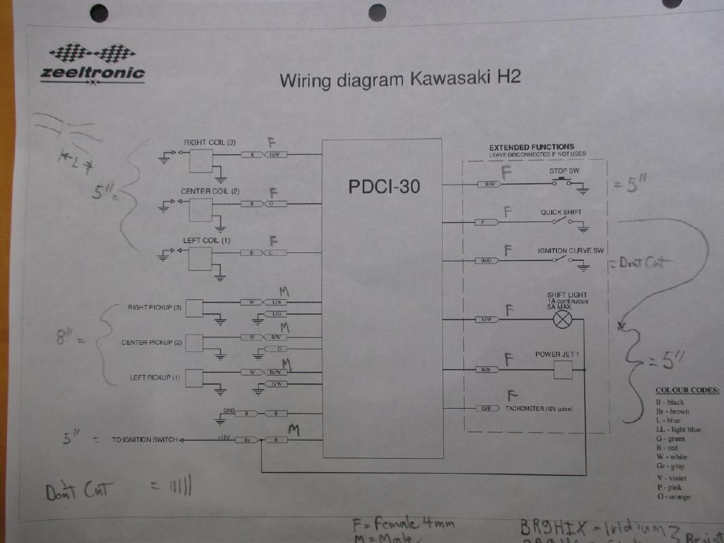
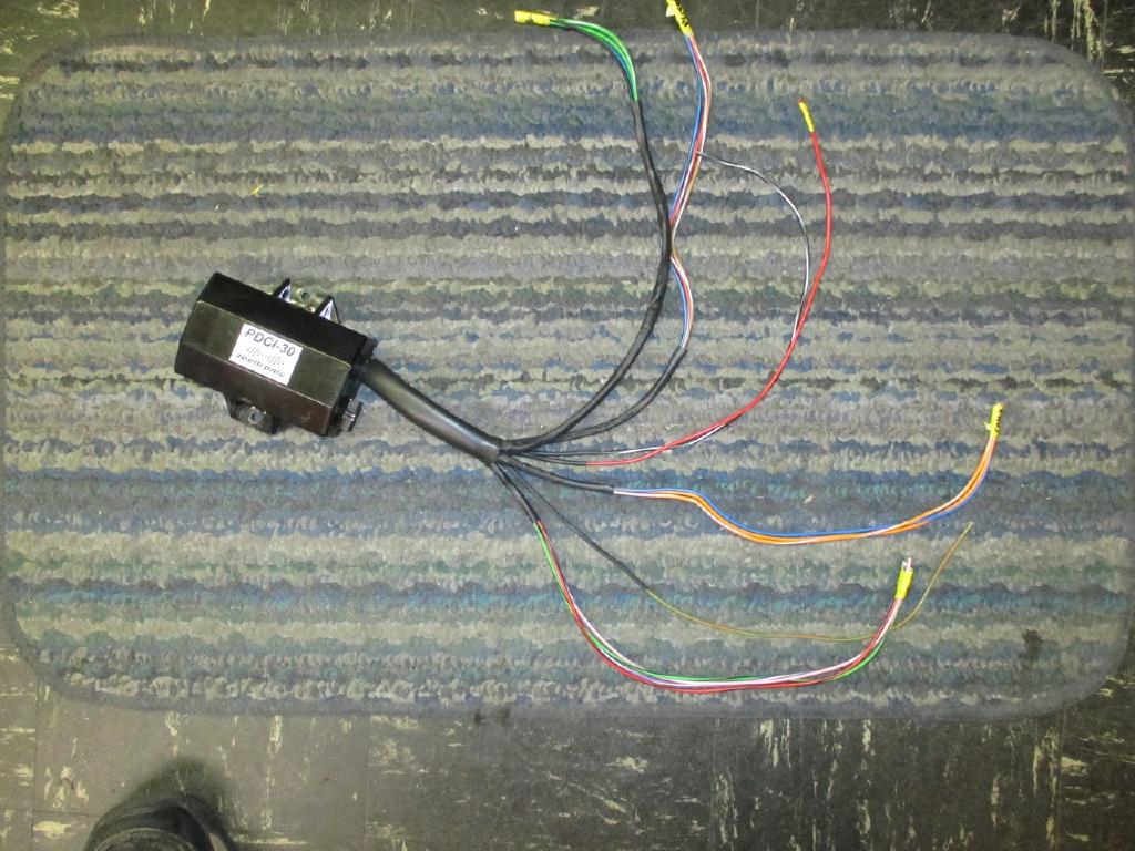
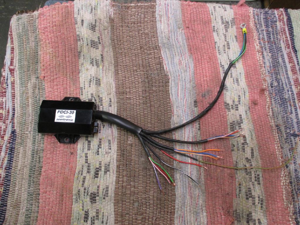
The wiring for the PCDI-30 is different than the VCDI-30 controller. The PCDI-30
comes with a long sleeve and 17 wires coming out of it. I have a connection
diagram that shows F or M for the connectors and an approximate wire length,
leave 4” on the big sleeve out of the zeel.
NOTE: In my diagram, the wire length to use is from the end of the 4” big sleeve
to the connector (so 5” is actually 5” +4” (the sleeve) from the zeel box). I
did the wiring so that I did not have to alter the H2 wiring harness and could
put my old CDI back on if needed.
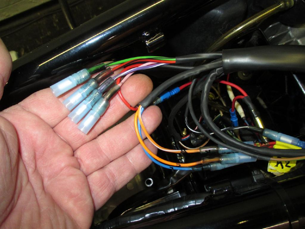
I bundled my groups of wires by purpose and then used heat shrink to separate the groups, turned out very nice and makes for a clean install, I then slide the heat shrink into the 4” sleeve about an inch and then heat them up. Don’t cut any wires yet.
The 3 prong connector to the old CDI Blue\Green\White is no longer used from
the Low\High speed coil.
The Zeel runs on switched +12 Volts, this is the BROWN wire coming out of the
harness Female, I made a 3 way connector M/F/F pigtail about 2” long (M is Male,
F is Female), it then goes to the Zeel Red M connector and the existing Brown M
down to the brake switch. Tie them all together.
Primary\Secondary (or the stripe)
Blue\Green, Green, Green\White and Black…….leave full length and bundled and
shrink with two tubes as this will go the ground where the CDI ground used to
go, you will need a round ground terminal, which I soldered it all together.
This also ties the 10 guage ground to the Engine.
Blue\Black=Right, Red\White=Center, Brown\White=Left and bundle 8” after the
Sleeve, M connectors to the Pickups
Orange\White=Right, Orange=Center and Blue=Left and bundle 5” after the sleeve,
F connectors to the Coils
Black\White by itself 5”, to Black\White F is the kill switch
Brown\Green full length to MAP switch F, I am just using a ground pigtail with
an M for now, will add a switch later. Unplugged for initial set up Map1 (plug
in or ground for Map 2).
Pink, Green\Brown, Violet\White, Red\ Black and Green\Black are bundled 5” from
the sleeve with F connectors; these are for future use and miscellaneous outputs
and are not connected at this time.
I used a DC grounded Soldering Iron and tinned the leads after I stripped them,
do NOT use a regular soldering iron or gun as the tip is electrified and could
destroy the electronics of the unit.
Crimp the Bullet connectors on well using a connector tool (Ideal), make sure
they will not pull off by tugging on them. Then use a lighter (whatever) and
heat shrink the connector tubes down till around the wire.
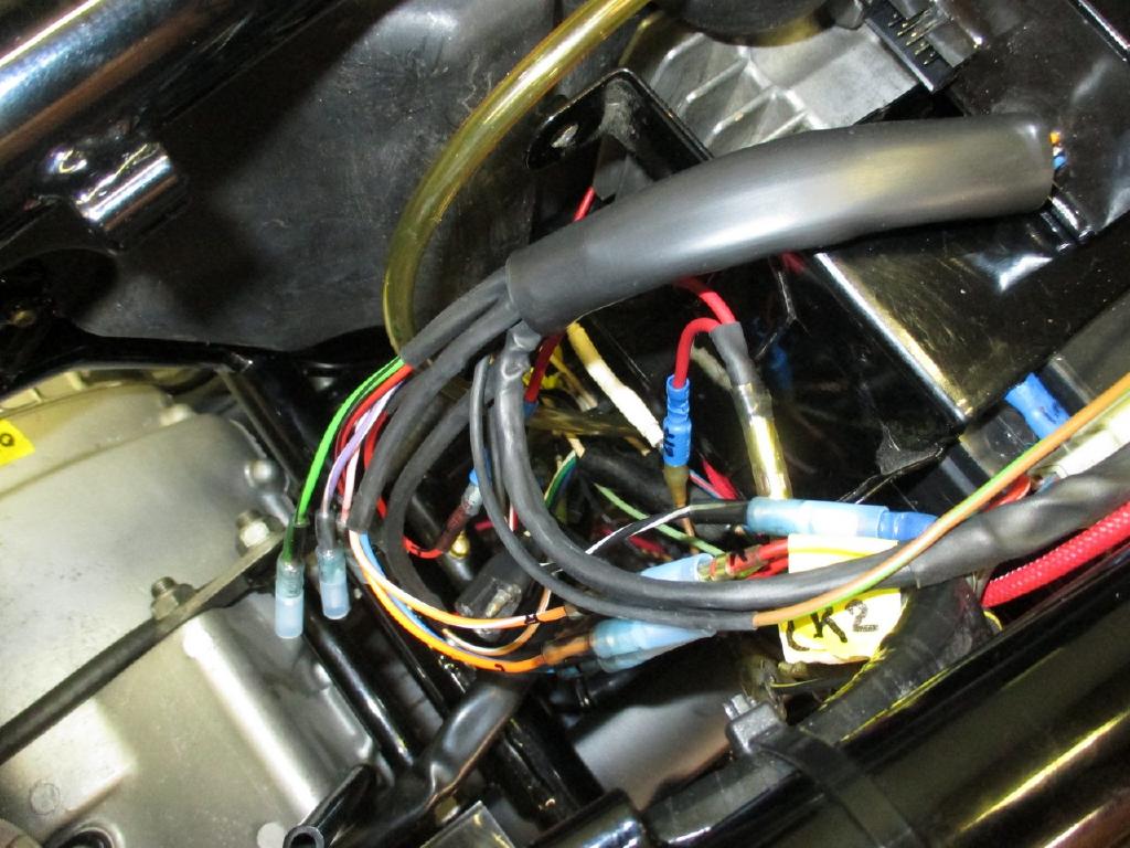
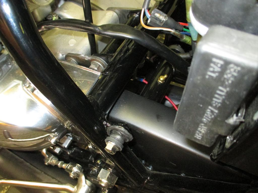
I removed my stock CDI and plate, the Zeel mounts well underneath where it
was, drill two screw holes and use two sheet metal screws, the wire bundle
heading towards the front of the bike and dropping down over the battery box.
Connect everything up, use some Ty-Taps loosely and connect the battery if
desired. The Zeel supports up to 18 volts in, the H2 can put out up to 16 volts.
You can run with the headlight on and drop that down, I got a Lakeland “Super
Regulator” from Jim Hobbs as it won’t pass more than 13.7 volts and won’t cook
your AGM battery (as fast anyway), or the Zeel unit.

Remove the Stator cover, and get access to the pick ups. I went to Ace and got Stainless Allen screws, note that the 3 for the plate are shorter (so it doesn’t hit stator rotor), then 6 for the pickups with washers and lock washers.
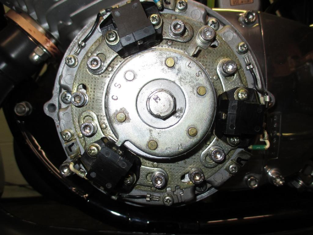
On the pickups, remove the little wire holder's on the right of each pickup
as this will bind. Also remove the black ground wire screws as this will limit
travel. Rotate the plate as far as it will go clockwise, you may want to leave
the three plate screws out to verify full travel, there is a notch at the bottom
you can fit a flat stubby screwdriver in to turn the plate. Install your three
plates screw and TAB. Move each Pickup as far clockwise as they will go, I set
the air gap at .020” between the rotor pick up and the wiper on the rotor. (You
may want to check the book; mine were at .014 before, which is too close as any
wobble can destroy the pickups). I then cut the corner of the little wire
holders as to not cut into the wires and then re-installed them. Now reconnect
the three black ground wires.
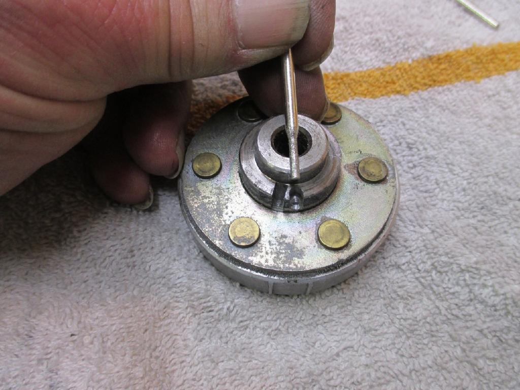
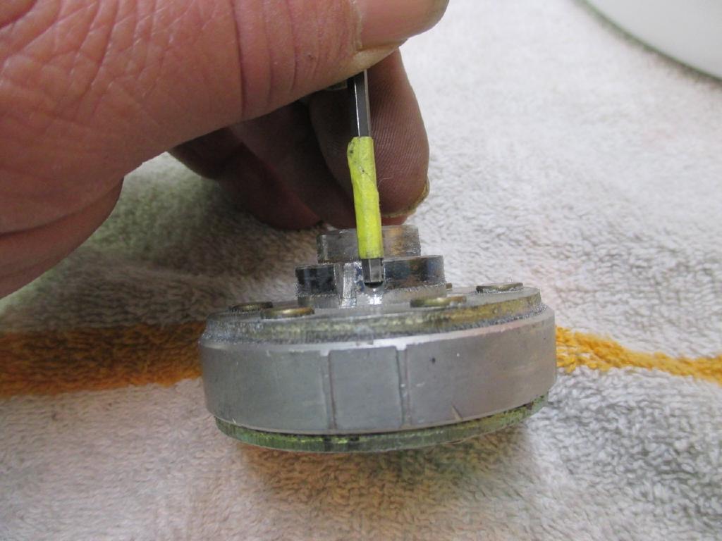
I had to Mod the rotor as in combination with the above turning the plate and
pickups, there was not enough separation between the Static angle and the MAX
advance in a curve (1 or 2 degrees is not enough time for the CPU to compute),
this caused a very slight misfire when the MAP hit a MAX advance point, it is
perfect now, so do both the above and rotor mod. Do not over do it on the rotor
Mod, though the Zeel says it allows for up 85 degrees Static, I have heard that
over 50 can cause issues (from someone)
I now have 44 degrees static angle possible, rather than drilling a hole in the
stator, I made a second hole\keyway in the rotor. I now have good separation
between 27 MAX advance in a MAP curve and 44 Static (17 degrees). This allows
plenty of time for the CPU to do it's computations, and in theory you could run
more than 27 degrees advance, I wouldn't on an H2, that's plenty.
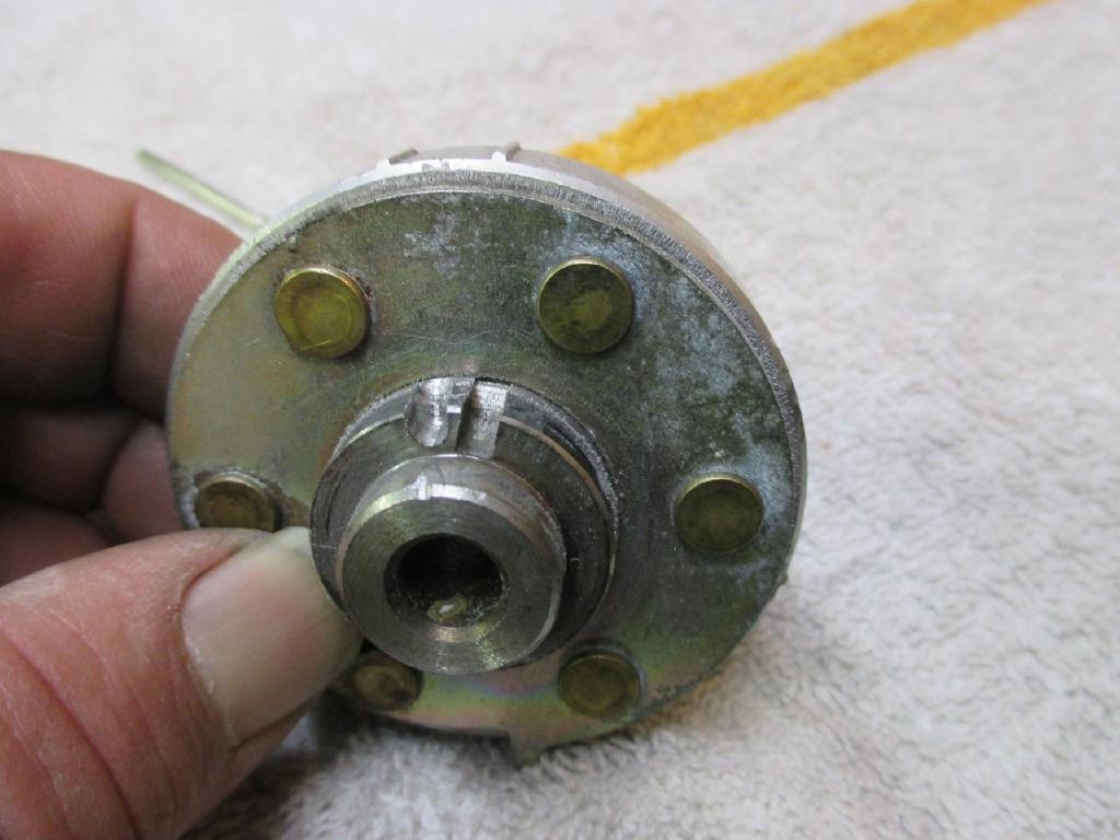
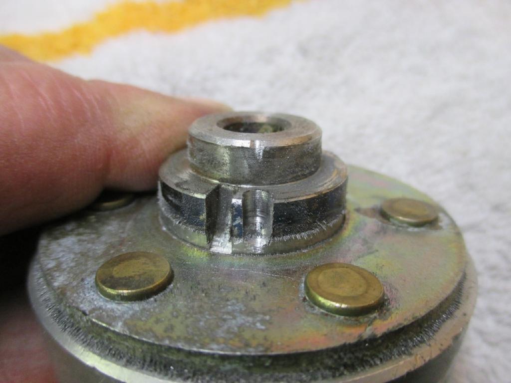
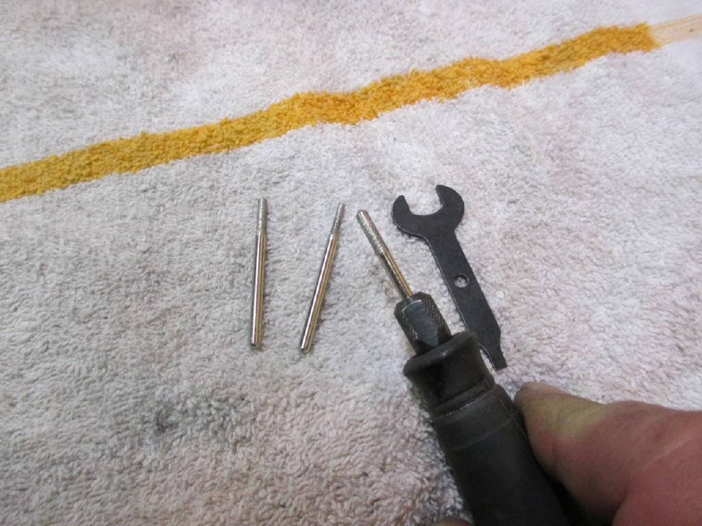
I used little diamond dremel's (From Harbor Freight) and just dug away on it as seen in the PIC below. Test fit, grind some more, test fit, until good and fits tight, then use plenty of Blue Loctite on the rotor bolt, mark a dot in the center of the rotor bolt with a sharpie for when using a timing light (aim at the dot).
Pull your plugs out and connect them and lay them on the heads, you can test from the Laptop, key ON, test fire, it will do L then C then R, should see a good spark on each, that verifies the wiring is correct.
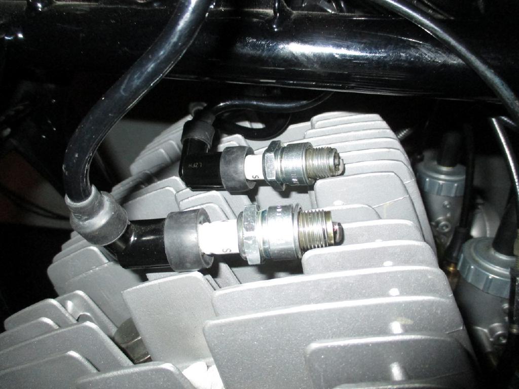
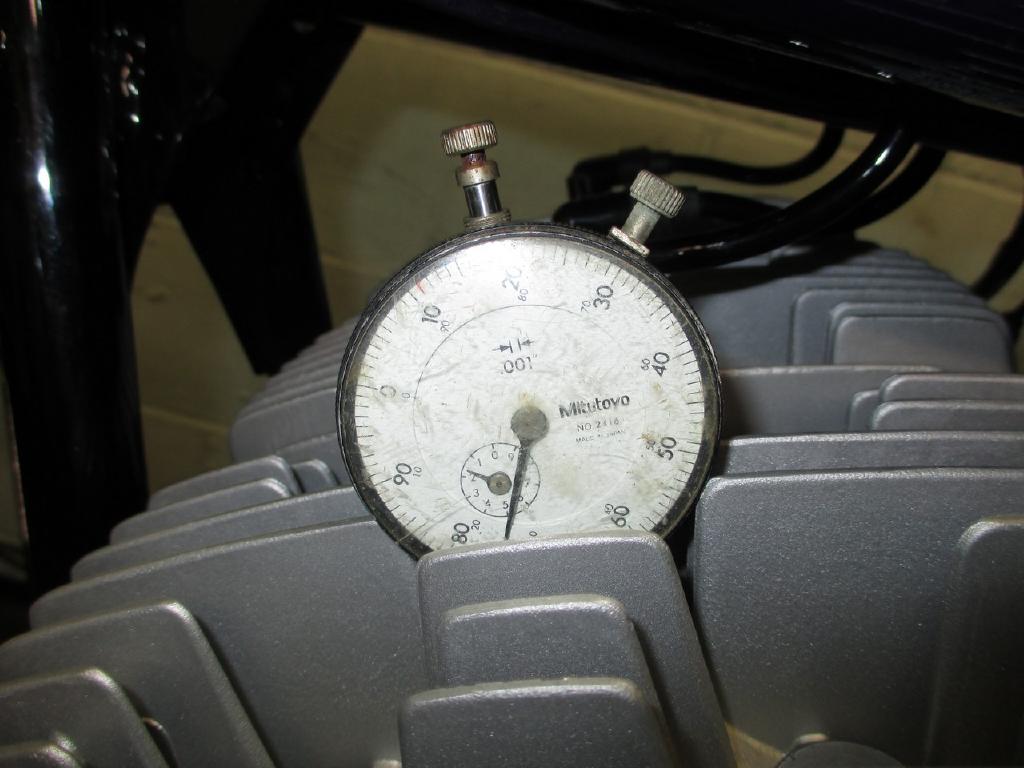
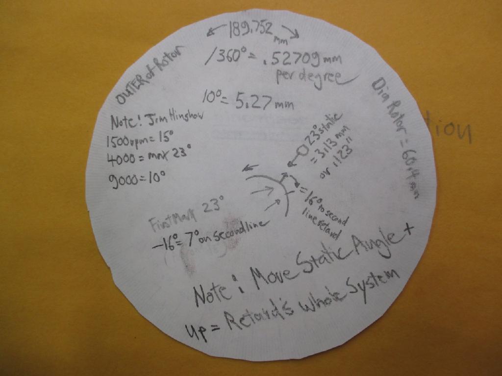
To set static timing, some people do their own marks and do it different ways. You must use a dial indicator in the L cylinder, H2 is 3.13mm or .124” before TDC which is 23 degrees advance (stock setting), The motor turns counter clockwise. I then moved my “TAB” to line up exactly with the “L” line on the rotor (the mark to left) as there are two marks. Line it up so that looking down from the tab to the mark straight down to the center of the stator bolt. This gives you a reference and a starting point. You can then mark a line before and after on the rotor for finer setting once ready to dial it in and 5.27 mm around the circumference of the rotor is 10 degrees from the initial setting.

I Would not attempt to fire the bike up to set timing, do this first !!!
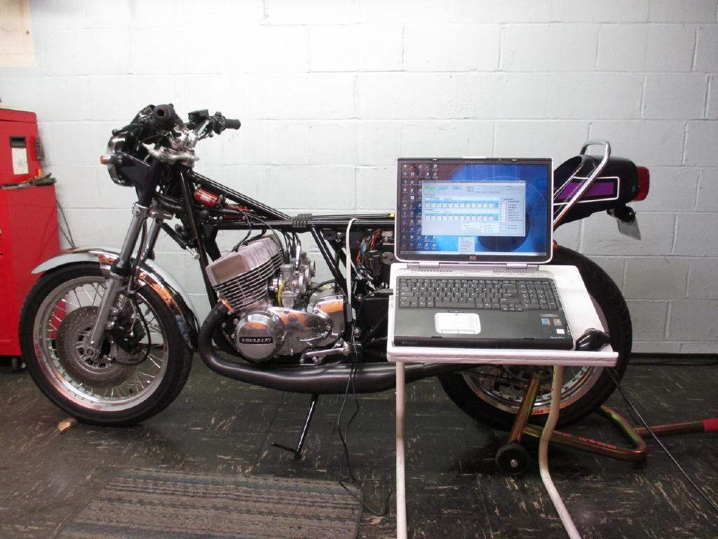
I got my buddy Andrew to put a drill on the motor and spin it (plugs out). I
used a drill with a 13mm, pencils to hold the carb slides up, Innova 3551 timing
light with the key ON, timing light works off a jump box 12volt (or the bike
battery), matched the previous tab after programming a flat MAP to 23 advance
across the board on all 8 points. Then set the STATIC in the zeel (mine is 44)
until the timing line matches with the Tab and the Dot on the rotor bolt with
the timing light. This will get you close enough to fire the bike up and reset
it at 4000 RPM next.
The Zeel program for the PCDI-30 and USB driver must be loaded on your laptop
and it is available from the Zeeltronics main website. You can use the handheld,
but it can be confusing, the laptop is very easy, I do like the handheld as a
back up.
When connecting, start the Zeel program and plug in the USB, then plug into
the PCDI-30 and it will read the unit (with the key off, on, running or sitting)
as does the handheld.
I used a flat curve on Map 1, just 23 across the board for initial setup (and a
basic Borut H2 map for Map 2). Check AUTO READ,Check MAP SW, 3 pickups, Static
angle 44 (On My Bike) more is retarded which is good for initial, ADVANCE at 0,
Delay at 30, Advance per CYL at 0 for now, Shift Light whatever 6800, Rev limit
whatever 9500, POWER Jet off, SMART SHIFT OFF.
8 points (MAP 1 flat, Borut H2 MAP2)
RPM MAP1 MAP2
1500 23 23
3000 23 26
4000 23 25
5000 23 24
6000 23 23
7000 23 22
8000 23 21
9000 23 20
When strobed and it shows a cyl to be slightly advanced, then program its value
"-" for that cylinder.
When strobed and it shows a cyl to be slightly retarted, then program its value
"+" for that cylinder.
Once you get the Left strobed with TAB and it lines up (my static was 44, main
advance at 0, each 8 curves set at 23), I then did each individual cylinder, I
had to do Left at -.7, Center at 0 was good, Right at -1.2……..now everything
lines up perfect at 23 degrees with the initial flat curve. At least One
cylinder should be at 0, or move your static so that one is zeroed, then adjust
the other two as pickups to a - value. This will give you the MAX static
capability possible.
When revving and watching the mark, it should not move as much as it did on the
early CDI’s because signal DELAY is preventing that I think, but that is effect
of the Pickup Signal's, the faster the rotor spins, the quicker they trigger,
which is why all H2's advance, that's why, 4000 RPM is where it should stop
using a Flat 23 Map.
It does not take much to be off a degree or two, so double check everything.
Now you can test the bike on MAP 1 flat, then try MAP 2 by plugging the switch
in, I noticed an immediate improvement. This could effect jetting, and NEVER go
over 23 MAX advance when at MAX Torque (5500 RPM ?) on the pipe or you can Deto
and Destroy the motor.
Here is a link to
an Excel file to calculate timing degrees and measurements.
Any .zee file, Maps, suggestions, jetting, etc, please post
Phil Mosher September 2017