Triple Maintenance Manual
All Kawasaki triples have three-cylinder engines. Basically, all are the
same, even though they have different dimensions for different displacements.
Some parts are interchangeable between the two series of motorcycles. The
powerplants are two-stroke cycle, air-cooled engines. All have horizontally
split crankcases and individual cylinders, each with its own cylinder head
(rather than a conventional one-piece cylinder block and a one-piece cylinder
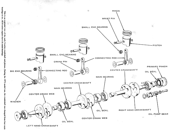
head). All of the crankshafts are built up out of separate pieces and are
pressed together. This makes them very durable in strenuous duty, but they
cannot be repaired except by the best equipped motorcycle machine shops. The
crank throws are 120° apart so that the cylinders fire evenly with three power
pulses per revolution of the crankshaft. This makes these
engines very smooth for their size and power output.
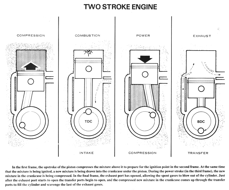
A two-stroke-cycle engine is the simplest type of internal-combustion engine,
although the mechanics of its operation are quite complex; it must be very
carefully designed. Kawasaki triples are built like three single-cylinder
engines hooked together in a line. Each "engine" has its own chamber in the
crankcase, and each has its own connecting rod between the crank and piston.
Each has its own cylinder head, carburetor, and exhaust pipe.
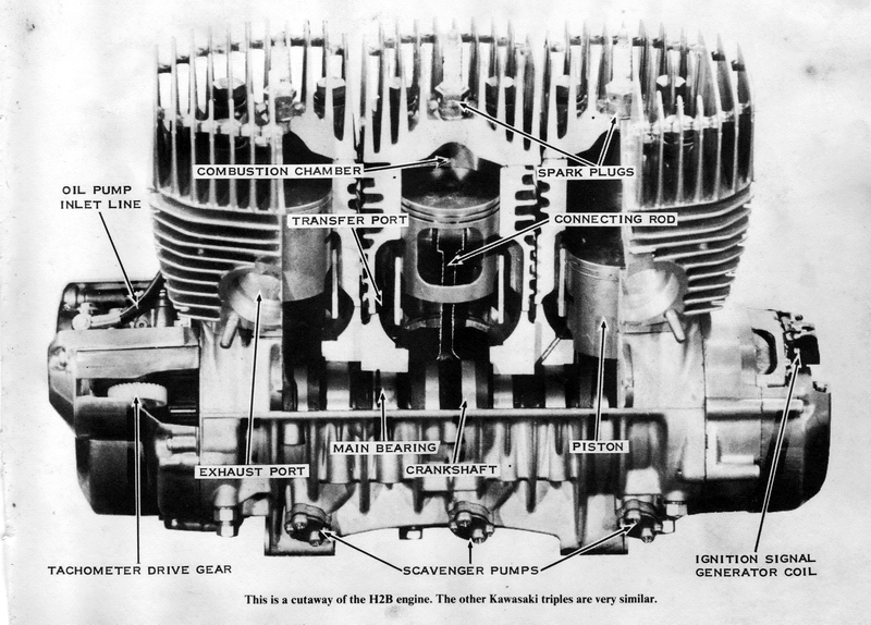
The ignition system is on the left-hand end of the crankshaft. On the S-series
models and the H1B model, this system is actually three separate battery/coil
systems, very similar to that found in an automobile but without the
distributor. The H1 and H1A models have a CDI system with a distributor. The H1D
and H2 models have three separate single-cylinder CDI systems, and the H1E has a
single CDI system that fires each of the three cylinders through a unique
low-tension distributor. (See Chapter 7, Electrical System Service, for more
information on the ignition system.)
The other end of the crankshaft has a gear that transmits the engine's power to
the clutch. The oil pump and the tachometer cable are also run off the
right-hand end of the crankshaft.
PRINCIPLES OF OPERATION
Two-stroke engine operation is quite complex. The Kawasaki triples are called
piston-valve or piston-port engines because they have an inlet port in the rear
of the cylinder that is controlled by the lower edge of the piston. The intake
port is closed while the piston is at the bottom of its stroke.
As the piston rises, its lower edge uncovers the port. The volume of the
crankcase (under the piston) is increasing because the piston is rising, so the
mixture is drawn from the carburetor into the crankcase. At the top of its
stroke, the piston starts back down and the intake
port is covered once again. The new mixture is trapped in the crankcase and
squeezed by the descending piston. Suddenly, the upper edge of the piston
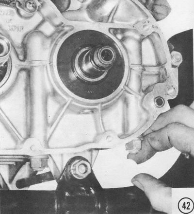
uncovers the transfer ports, which connect to the crankcase; the mixture blows
up through them and into the cylinder above the piston.
After passing the bottom of its stroke, the piston rises again and traps the
mixture above it as it closes the transfer ports. The mixture is compressed
above the piston to a fraction of its former volume, then suddenly ignited by a
spark across the electrodes of the spark plug. The resulting combustion forces
the piston down. About halfway down, the exhaust port is uncovered and the
burned gases escape into the muffler. A fraction of a second later, the transfer
ports open and the next charge of mixture is admitted. Because the engine
produces a power pulse at every piston during each crankshaft revolution (and
there are three pistons), three power pulses are produced for each revolution.
At a speed of 5,000 revolutions per minute, the engine is producing 15,000 power
pulses every minute, or 250 pulses per second. This makes the Kawasaki triples
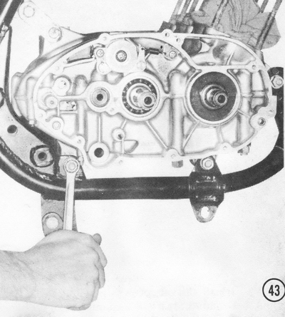
very smooth and powerful for their size.

GENERAL SERVICE INSTRUCTIONS
Before removing the engine from the chassis, wash the entire motorcycle
thoroughly to remove dirt, mud, and grease. A clean machine is easier to work on
and lessens the possibility of dirt or other abrasive foreign matter getting
into the engine.
Have a clean place to work prepared before you start. It is best to have a bench
or table to work on with your tools and equipment handy.
Use small boxes, muffin tins, egg cartons, and so forth to keep small parts
separate and in order. When the engine is on the bench, try to lay out the parts
removed in a position corresponding to their positions on the engine, and in
small groups. This will make assembly easier and help prevent mixing or losing
small parts.
FASTENERS
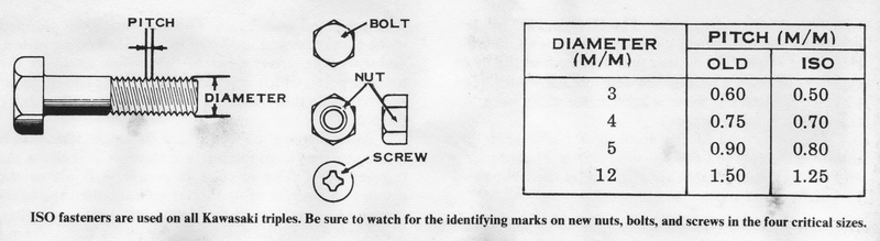
All of the nuts, bolts, and threaded parts used on the Kawasaki triples are
metrically sized and threaded according to the standards of the International
Standards Organization (ISO). The ISO standards for threaded fasteners were
accepted in Japan in 1967. CAUTION: Fasteners made before that time may be
different. All of the Kawasaki triples have been made after 1967, so they
use all-ISO fasteners. The critical sizes that were changed when the ISO
standards were accepted are 3mm, 4mm, 5mm, and 12mm thread sizes. All fasteners
in these sizes that are ISO standard have a punch mark on one end to identify
them. If any fasteners of these sizes must be replaced, be sure to get ISO
parts. If there is any doubt, compare the threads on the new and old parts to be
sure your motorcycle will not be damaged. CAUTION: Do not ignore the
possibility of conflicting threaded parts, which will cause difficulty.
Many different-length screws are used to install the engine covers. To avoid
improper assembly and save time, lay out the screw hole pattern on a piece of
card board during disassembly, and then insert each screw into its respective
hole in the cardboard pattern as it is removed. The screws will then be
correctly arranged for assembly. If the screws are mixed up, the correct ones
can be found by trying different-length screws in each hole until one is found
that protrudes about 1/8" before the threads engage. CAUTION: If too long
screws are used, they can bottom before the cover is tight and allow oil
leakage. If a short screw is used, the threads will strip.
ORDERING PARTS
As you disassemble the engine, you will find that certain parts must be replaced
regardless of wear. The following parts should always be included with each part
order; Nearly all of the gaskets, including the head gaskets, must be replaced
whenever they have been removed. You will need three head gaskets. three
cylinder base gaskets, three exhaust gaskets, one left-hand engine cover gasket,
and one right-hand engine cover gasket. The ignition cover gasket and the
distributor cap gasket can be reused. The crankcase halves are joined with
Kawasaki Bond, a silver-colored adhesive sealant. The main crankshaft bearings
should be seated with a bearing-locking compound such as Kawasaki Super Lock-K
or Loc-Tite Formula B. If the machine is to be used in competition, all
fasteners must be secured with a thread sealant, such as Kawasaki Lock-K or Loc-Tite
Formula A.
Always purchase two new piston pin circlips for each piston, and all-new
transmission circlips. These new parts must be used to insure a reliable repair,
as the old parts have been strained and could break.
The oil seals at the ends of the crankshaft should be replaced at each major
engine overhaul. Always replace the lock plates under the clutch hub nut, engine
sprocket nut, and primary pinion nut.
GENERAL TOOLS
FEELER GAUGES
These are used to check piston ring end gap and side clearance, shift fork
clearance, contact point gap, clutch plate warping, magneto air gap, and other
wear specifications. A feeler gauge set with a range of 0.001" to 0.060" will
cover all requirements.
COMPRESSION GAUGE
This gauge is used to check the condition of the piston, piston rings, and
cylinder bore.
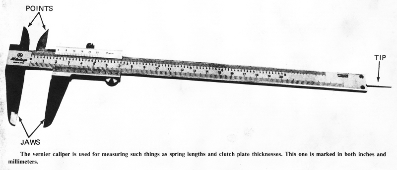
VERNIER CALIPER
This is a measuring instrument which is accurate to 0.001". It is used to
measure the thickness of clutch plates, thrust washers, shims, and shift forks;
also the length of clutch springs, clutch pushrods, and the diameter of thrust
washers. This is an invaluable tool which is well worth the small investment
involved.
MICROMETER
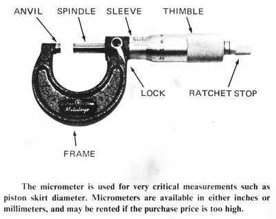
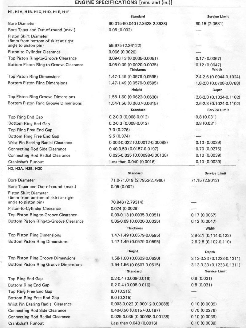
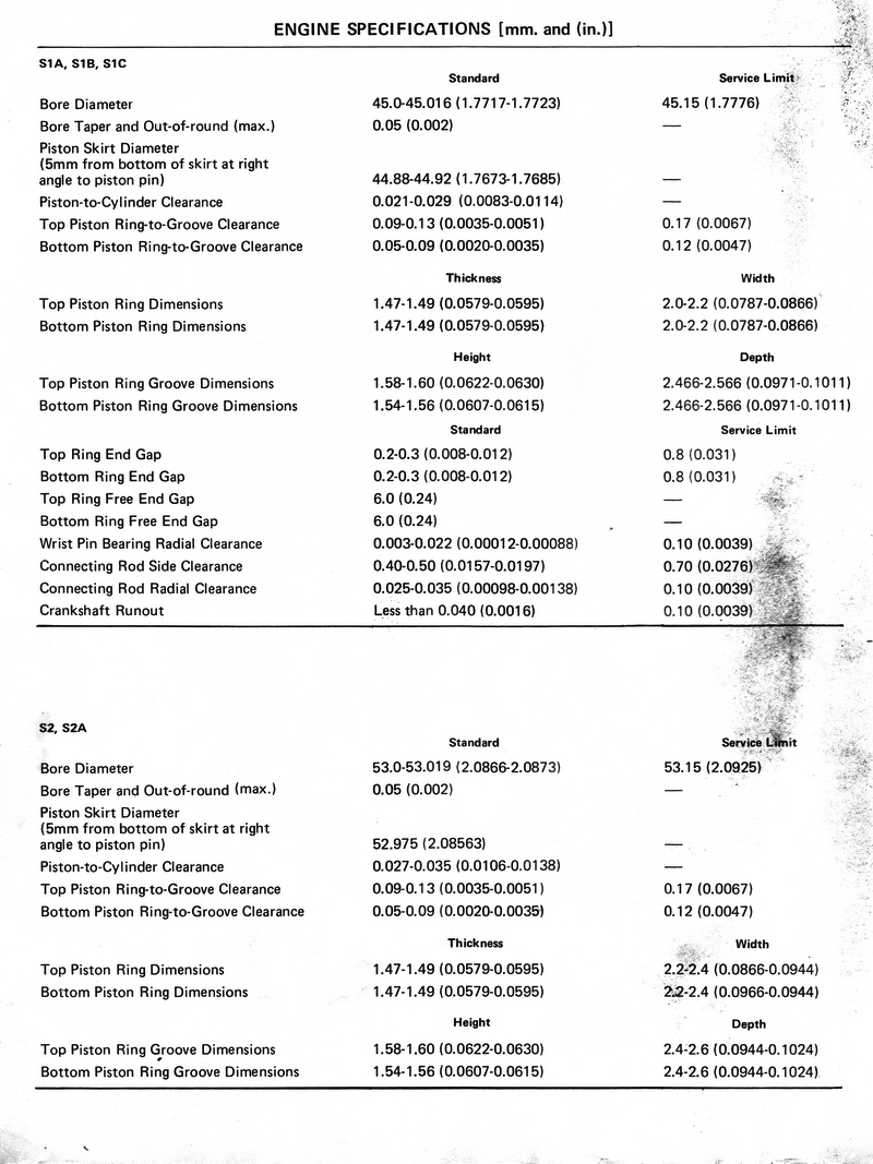
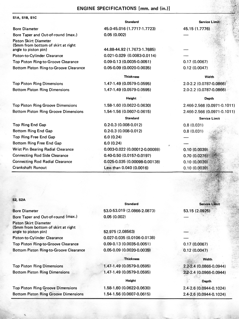
This instrument is required for measuring the piston diameter and determining
piston clearance. A 3-inch micrometer is used for all models except the S1,
which requires a 2-inch micrometer. A telescopic anvil can be used to transfer
cylinder bore measurements to the micrometer.
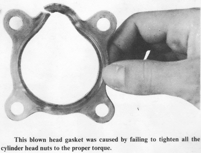
TORQUE WRENCH
A small torque wrench is necessary for tightening the cylinder head bolts to
prevent cylinder head warpage and blown head gaskets. A 600 lb-in. or 50 lb-ft.
torque wrench is the proper size.
CIRCLIP PLIERS
These are used to remove the circlips which fasten the gears to the transmission
shafts. External (spreading) pliers are used where the circlip fits over a
shaft. Internal (squeezing) pliers are required for a circlip which fits inside
a gear.
METRIC SOCKETS
A full socket set from 10mm through 27mm hexagonal sizes is needed. A 3/8" drive
ratchet, extensions, and a speed handle are also recommended. NOTE: Six point
sockets are best because they contact and support a larger area of the hexagonal
flats. Twelve point sockets are valuable in confined locations, where it is not
possible to move the handle enough to engage the socket with the nut.
METRIC WRENCHES
The wrenches included in the Kawasaki tool kit are adequate for any repair job;
they cover the range of sizes of most fasteners used on the motorcycle.
COMBINATION VOLTMETER-OHMMETER-AMMETER
This device is required to check the electrical equipment for the cause of
failure.
SPECIAL TOOLS
IMPACT SCREWDRIVER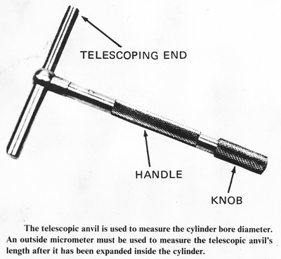
A reversible impact screwdriver, with at least two Phillips-headed screwdriver
bits, is absolutely necessary for disassembling and assembling the engine cases.
CAUTION: It is impossible to tighten the Phillips headed screws adequately
without this tool. By sharply
hitting the end of the impact driver with a hammer, a strong twisting force is
applied to the screw without damaging the slots in the screw head. A standard
3/8"-square drive type is best so that you will be able to use universal bits
and extensions. NOTE: Make sure that the tool can be used in both directions
for removing as well as installing.
LOCK PLATE
This device keeps the crankshaft from turning while removing the primary pinion
nut or alternator rotor. It is made of brass to prevent damage to the piston
skirt or connecting rod small end.
CLUTCH HUB WRENCH
This tool is used to keep the clutch hub from turning while loosening or
tightening the clutch hub nut. To make your own, have a 12-inch length of 3/8"
rod welded or brazed to the outer diameter of a clutch steel plate for your
specific model.
WRIST PIN PULLER
This tool is used to pull the wrist pin out of the piston and connecting rod
small end without damage. It is also used in assembling these parts.
PISTON POSITION DIAL INDICATOR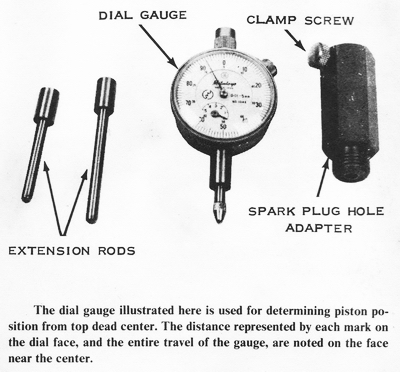
This indicator is essential for accurate ignition timing. A kit is available
from Kawasaki dealers that contains all of the extension spindles needed to
service all of the three-cylinder models.
CONTACT POINT CONTINUITY DEVICE
This audio-visual signal device indicates electrically when the points open. It
is essential for exact ignition timing.
SPANNER WRENCHES
These tools are used to adjust the steering bearings in the frame head.
SPROCKET WRENCH
This wrench is used to hold the drive sprocket and transmission driveshaft when
loosening or tightening the sprocket nut. There are commercial tools available,
but a short length of the chain for your particular machine and an 18-inch
length of pipe large enough to fit over the end of the chain will do the job.
Insert the chain into the end of the pipe, drill two holes, and insert a bolt
through the pipe to hold the end link.
CRANKCASE LEAKAGE GAUGE
This gauge is required to check the crankshaft seals and the crankcase for
compression leakage. To check a crankcase, screw the fitting into the spark plug
hole and block off the exhaust and intake ports. Pump up crankcase pressure to 6
psi. CAUTION: Don't overpressurize the crankcase or you will force out the
crankshaft seals. Make sure there is no leakage from the exhaust and intake
ports. If the gauge indicates a pressure-drop rate of more than 1 psi per
minute, leakage is excessive. Use soapy water to locate the source.
OVERHAULING THE ENGINE
DISASSEMBLING
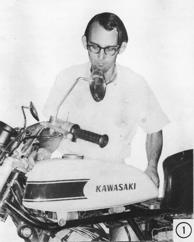
1) Remove the fuel tank. Early H1 fuel tanks mount with two bolts in front, at
each reflector, and one under the front of the seat. On other models, remove the
rubber strap under the front of the seat, or lift up on the rear of the tank to
pull the mounting pin out of the rubber block on the frame. Slide the tank off
to the rear.
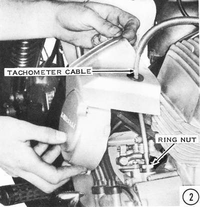
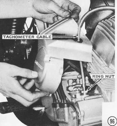
2) Remove the oil pump cover, then unscrew the tachometer cable ring nut.
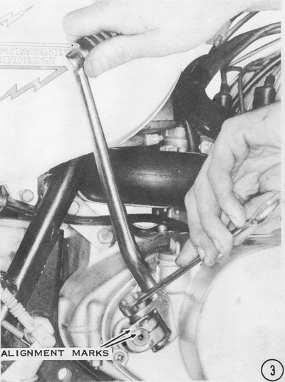
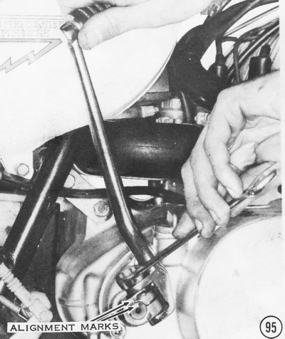
3) Remove the kickstarter pedal boss bolt completely. Make a reference mark on the boss and on the end of the shaft, and pull the boss off the shaft.
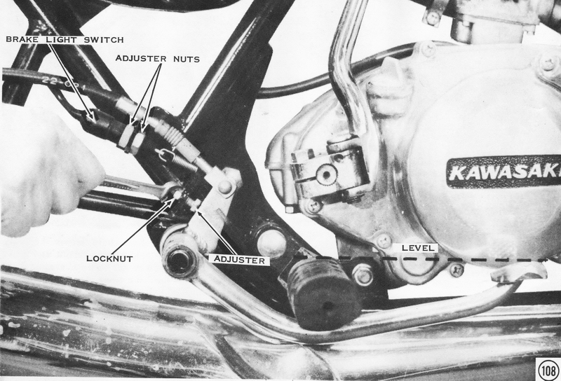
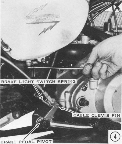
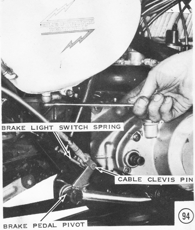
4) Remove the oil tank cover, then remove the banjo bolt from the bottom of the oil tank. CAUTION: Do not lose the washer on each side of the banjo fitting. On models with a plastic oil line, pull the line off the nipple on the bottom of the tank. The oil tank does not need to be removed. Disconnect the brakelight switch spring, then pull out the brake cable clevis pin. Remove the cotter pin and washer from the brake pedal pivot. Carefully pull the brake pedal off the pivot. CAUTION: The return spring is under tension. It can fly off suddenly. Take out the footpeg bolts and remove the footpegs.
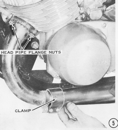
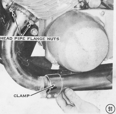
5) Loosen the two muffler-to-header-pipe clamping screws on each exhaust pipe. Remove the front and rear muffler mount bolts, then slide the mufflers off to the rear. Remove the two header-pipe-flange nuts and their lockwashers, remove the header pipes, and discard the gaskets.
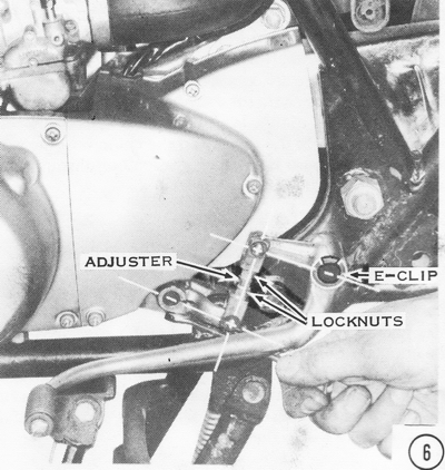
6) Remove the shift lever clamp bolt. Take off the E-clip and slide the shift pedal off its pivot shaft.
7) Loosen all air cleaner clamping screws, then remove the air cleaner silencer horn and the air pipe. Take out the air cleaner mount screw and remove the air cleaner. If the carburetors are to be disassembled, unscrew the carburetor caps, then pull the slides out of the carburetors. Carefully drape the slides and cables over the frame so they are out of the way. If the carburetors are not going to be disassembled, loosen the intake manifold clamp screws, then pull the carburetors off the manifolds. Drape the carburetors, with the cables attached, over the frame and out of the way. The intake manifolds do not need to be removed unless they are leaking or unless the ports are to be modified.
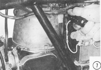
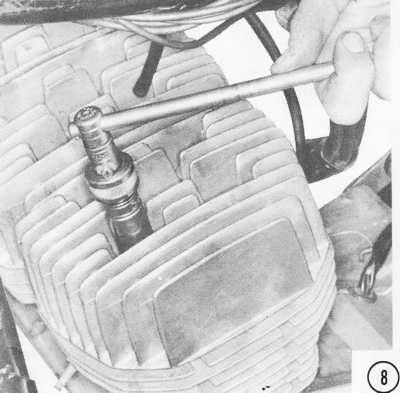
8) Remove the head nuts and their lockwashers. Lift the heads off the cylinders, and then separate the head gaskets from the heads. The head gaskets must not be reused because they become hard from engine heat and will not seal properly.
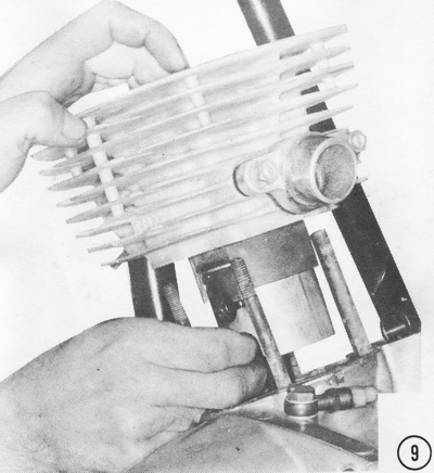
9) Pull the cylinders straight up from the pistons and the cylinder studs. Carefully scrape off the old cylinder base gasket. CAUTION: Be careful not to gouge the pistons by the threads on the studs if the pistons are to be reused.
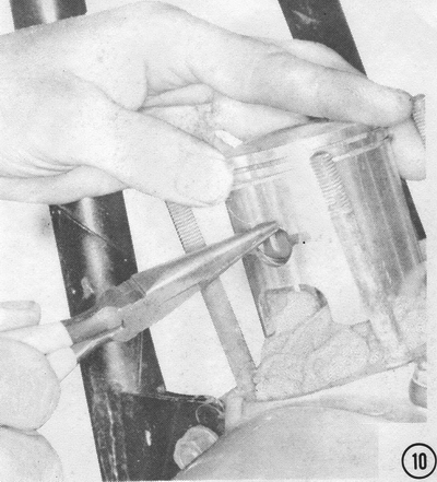
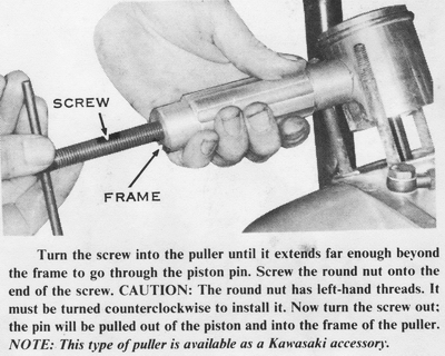
10) Stuff rags under the pistons to prevent anything from falling into the crankcase, especially if the cases do not have to be split. Remove the piston pin circlip. Usually the piston pin will slip out easily. If not, use a piston pin puller as illustrated. Lift the piston straight off the connecting rod. Slip the wrist pin bearing out of the connecting rod. Spread the piston rings lightly with your fingers, and then lift them off the piston. If they are stuck, soak the piston in a carburetor-cleaning solvent for a few hours.
11) Push down the locking ring on the neutral switch terminal, then pull the wire out. Remove the sprocket cover by taking out the three screws holding it to the crankcase.

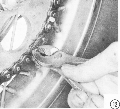
12) If the chain is not an endless type, remove the chain clip, and then pull the chain out of the frame.
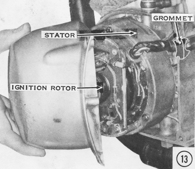
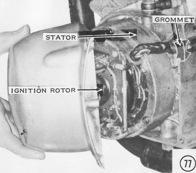
13) Remove the alternator or ignition cover. Unscrew the bolt in the center of the rotor, and then pull off the ignition rotor. Take out the three screws holding the stator in place, then pull the stator straight off the crankcase. The grommet can be pried out of the notch in the case. Leaving the wiring connected, carefully hang the stator over the frame and out of the way. If the stator is to be replaced, disconnect all of the plugs holding the stator wiring loom to the main wiring loom, then pull the wires free of the frame. CAUTION: Note the routing of the wiring loom to facilitate the installation of the new one.
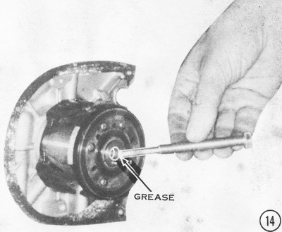
14) Using the rotor puller (available as a Kawasaki special tool), remove the
ignition rotor. Grease the tip of the rotor puller and its threads lightly
before using it. NOTE: The alternator rotor has to be removed only to replace
the left-hand crankshaft seal. The rotor cannot be easily removed with the
crankshaft out of the engine; therefore, if necessary, it is best to remove it
at this time.
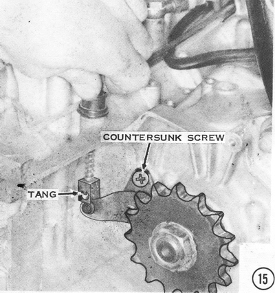
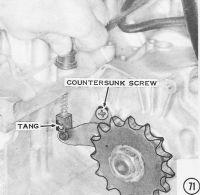
15) Bend the tang away from the cable nipple and slip the cable out of the slot in the cable holder. Pull the cable up and out of the case; allow it to hang down in front of the engine. Take out the two countersunk head screws that hold the clutch release mechanism. Pull the release mechanism and the short pushrod out of the case.
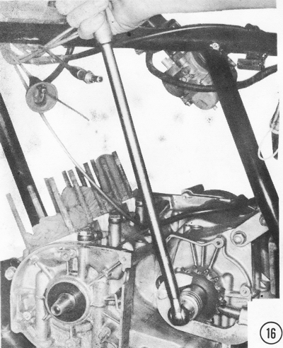
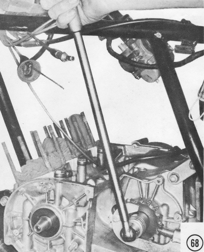
16) Fold down the tab of the lock plate on the sprocket nut. Using the universal sprocket holder available as a Kawasaki special tool), remove the sprocket nut, the lock plate, and the sprocket. If the motorcycle has an endless type chain, let it hang from the swing arm pivot.
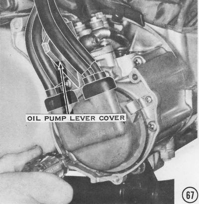
17) Take out the two screws and clips that hold down the distributor cap. Remove the distributor cap, high-tension wiring, and large rubber grommet together, and then drape them over the frame and out of the way. The coil high-tension lead can be removed from the coil if necessary. Remove the oil pump lever cover.

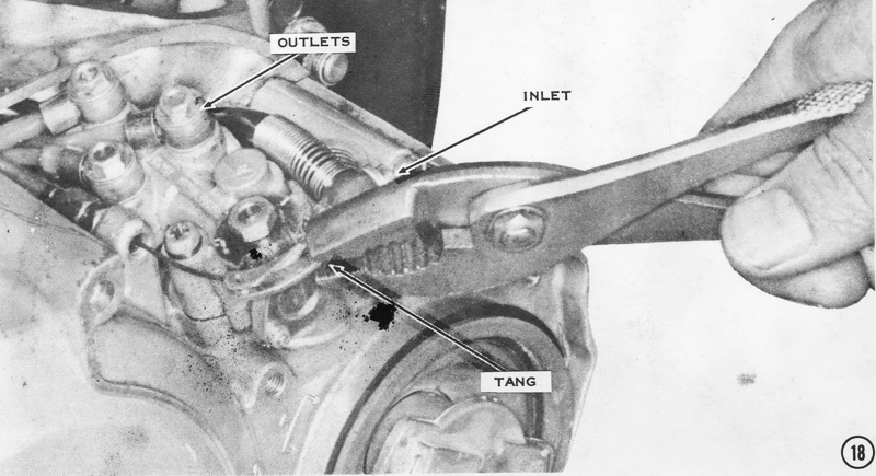
18) Bend up the tab on the oil pump lever. Unscrew the oil pump cable adjuster
(near the oil pump), then remove the cable. Take out the inlet banjo bolts and
the three or four outlet banjo bolts. CAUTION: Each banjo fitting has an
aluminum washer on each side. Do not lose them. NOTE: Some models have a
three-way lock tab instead of the upper washers on the outlet. Take out the
two screws and remove the oil pump. Remove the three banjo bolts that hold the
oil lines to the crankcase, then pull the oil lines free of the engine. NOTE:
Each oil line is a different length, but all the outlets are of equal output.
Don't worry about mixing them up.
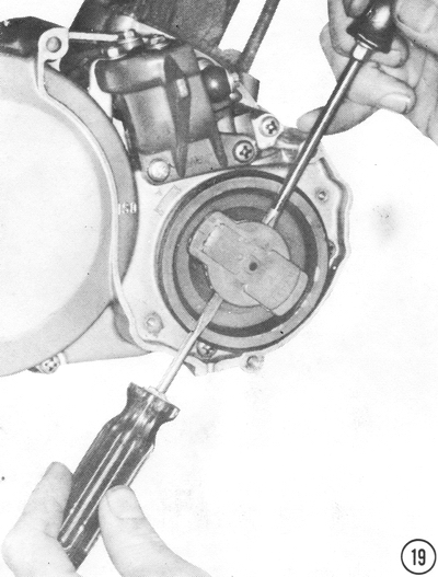
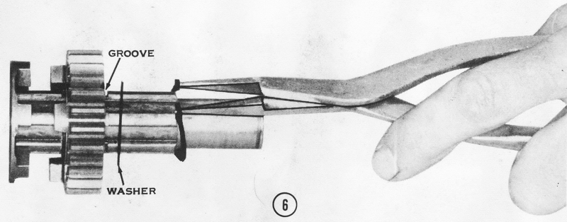
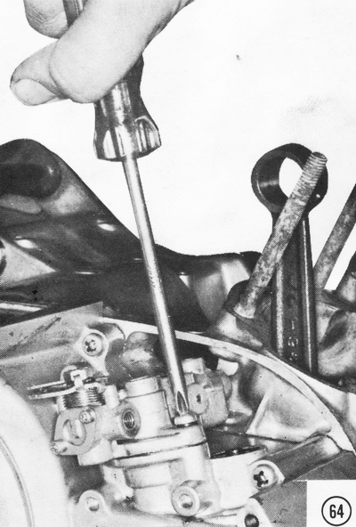
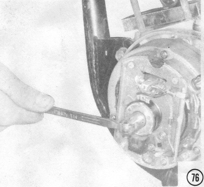
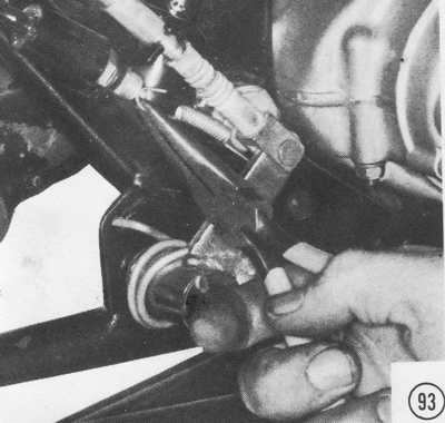
19) .Gently pry the distributor rotor loose with two screwdrivers as shown. If white stress marks show on the rotor during removal or on the gray plastic insulator behind it. replace them, as their dielectric strength has been decreased. Remove the right-hand engine cover at this time. CAUTION: Be very careful to remove all the screws to prevent breaking the cast aluminum cover.
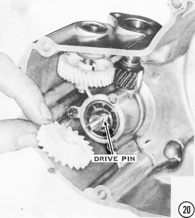
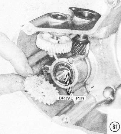
20) If the right-hand engine cover is to be disassembled, pull the two vertical shafts out the top with pliers. CAUTION: Do not lose any of the drive pins or thrust washers on these shafts. Remove the nut holding the distributor drive gear onto the distributor shaft, and then pull out the drive pin. The distributor shaft comes out from the other side. On S-series models, remove the two screws holding the tachometer drive gear bridge in place.
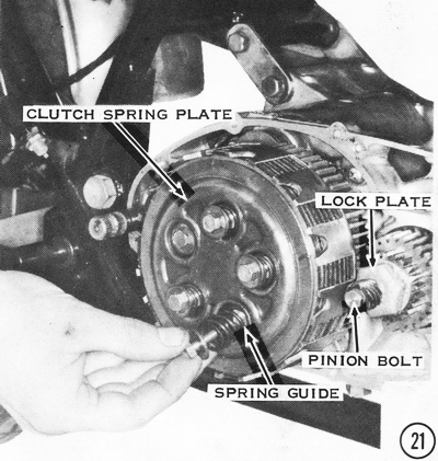
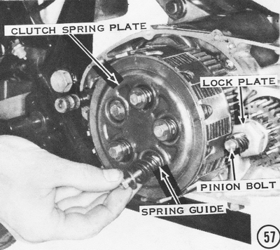
21) Remove the distributor drive pinion bolts from the end of the crankshaft. Lift off the pinion and the drive plate under it to expose the primary pinion nut. Flatten the lock plate, then remove the primary pinion nut. The two gears can be removed after taking off the clutch. Unscrew the five clutch-spring bolts, then remove the clutch springs, their guides, the spring plate, and the clutch plates as a unit. NOTE: On H2's, it will be possible to remove the outer two clutch plates before removing the clutch housing holder ring, which circles the clutch housing to prevent its expansion at high engine speeds. This ring can be slipped off over the outer end of the clutch housing fingers. Take out the clutch pusher, which is in the center of the clutch hub.
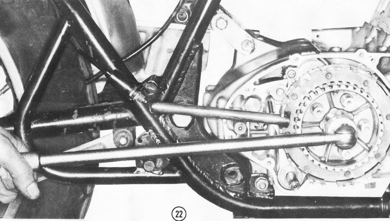
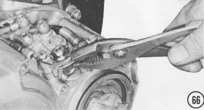
22) Flatten the lock plate under the clutch hub nut. Using a clutch holder tool, as shown, remove the clutch hub nut. CAUTION: Do not allow the handle of the clutch holder tool to rest on the kickstarter shaft or on any other part of the engine. Pull out the clutch hub, clutch housing, and clutch bushing. CAUTION: Do not lose the thrust washers between the clutch hub and housing and from between the clutch housing and the engine case. The crankshaft pinion can now be removed. CAUTION: Do not lose the Woodruff key in the crankshaft. If it is lost or damaged, it must be replaced with a genuine Kawasaki part or its equivalent because it is specially hardened and in a critical spot; it is dangerous to use a part made from untreated metal.
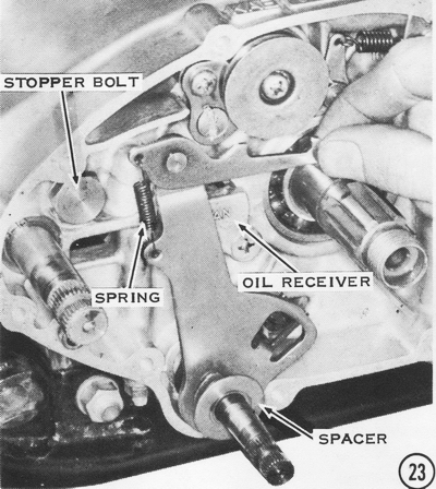
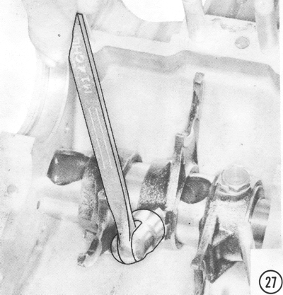
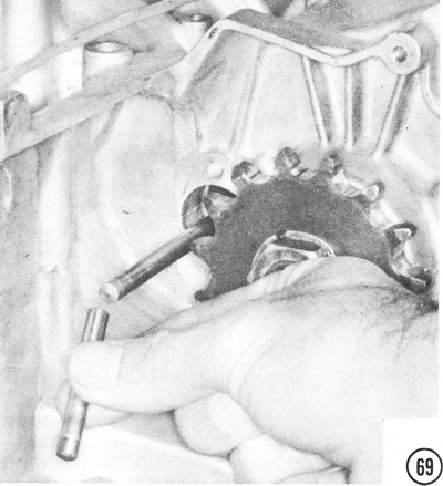
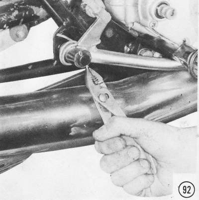
23) Pull the gear change ratchet mechanism away from the shift drum, as shown. then slide the entire shift shaft assembly out of the engine case. Remove the oil receiver screw and take out the oil receiver. Carefully remove the kickstarter shaft stopper bolt. CAUTION: This will allow the shaft to rotate clockwise suddenly because of spring tension.
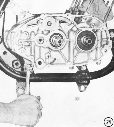
24) Remove all the engine mount bolts. Take the upper rear mounting bracket off first. CAUTION: There may be shims between the mounting lugs on the engine case and the frame lugs. Note where each one goes, so they can be put back in the right places. Lift the engine straight up until it clears the lower frame lugs. It can be taken out from either side of the frame.
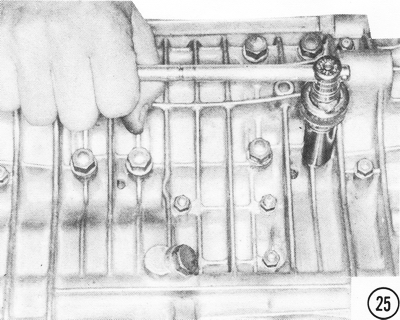
25) Turn the engine upside down on the bench. Remove the nuts holding the engine cases together. There are twelve large nuts and fifteen small ones. CAUTION: Be sure to remove all the nuts before trying to split the cases.
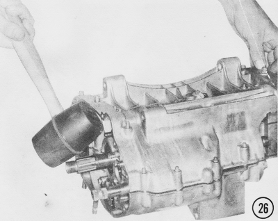
26) Strike the lower case half gently with a rubber mallet to loosen it. Lift it
straight off when it is loose. CAUTION: Do not use a screwdriver or other
tool between the case hales to pry them apart or you will damage the mating
surface and cause the engine to leak oil or air. This will cause extensive
engine damage.
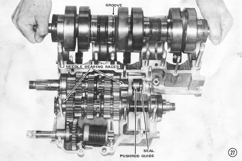
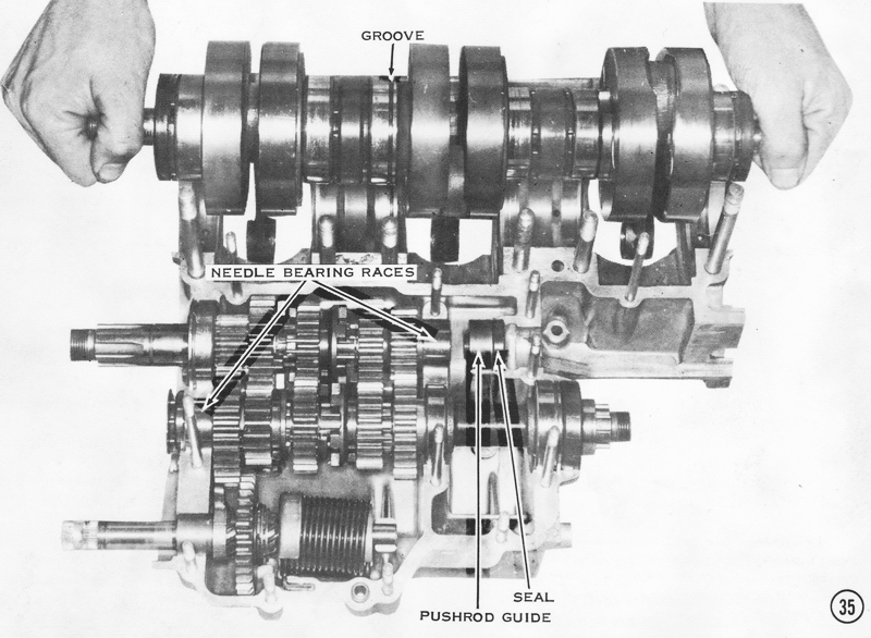
27) Lift out the crankshaft, two transmission shafts, kickstarter shaft, clutch
pushrod guide, and seal. CAUTION: Do not drop the needle bearing outer races
off the ends of the transmission shafts, because they are loose and could be
damaged.
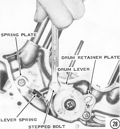
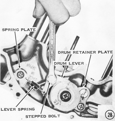
28) Remove the spring anchor plate, stepped bolt from the drum lever, and drum
retainer plate. CAUTION: The countersunk head screw on the drum retainer
plate is staked in place and may require an impact tool to loosen it.
29) Flatten the lock plates, then remove the shift fork bolts. Slide the shift
drum, and any fork rods, out of the engine case to free the shift forks.
30) To disassemble the kickstarter shaft, first pull off the kickstarter spring guide. Push the spring to one side to free it from the hole in the shaft, then take it (and the holder plate) off the shaft. The holder is secured with two E-clips. Remove these with a small screwdriver. Using circlip pliers, remove the large circlip on the splined portion of the shaft to allow the gear to slide off. Remove the small circlip on the other end of the shaft to take off the bushing.
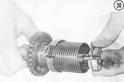
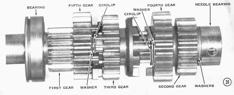
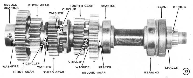
31) To disassemble the driveshaft, slip off the needle bearing outer race on the opposite end of the shaft from the clutch. Remove the small circlip under it, needle bearing, three thrust washers, and two gears. Remove each circlip in turn to free the rest of the gears. The smallest gear, 1st gear, is integral with the shaft. The ball bearing comes off the other end of the shaft. For ease of assembly, as each part is removed from the shaft, thread it onto a wire. This will keep the parts in the correct order and make identification of each gear simple.
32) The output shaft is disassembled in much the same way as the driveshaft. The
small ball bearing comes off with the gears. On the other end, an O-ring is
squeezed inside the outer end of the bushing. It must be removed with a sharp
instrument. The bushing, seal, and ball bearing will then slip off.
CLEANING AND INSPECTING
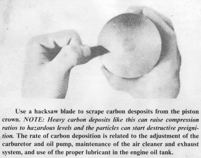
Scrape the carbon out of the exhaust ports of the cylinders, off the top of the
pistons, and from inside the cylinder heads with a wooden stick. Clean the
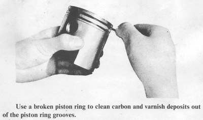
piston ring grooves with a broken piston ring. CAUTION: Be careful not to
score the top of the pistons or the bottom of the cylinder heads, because this
invites rapid carbon accumulation which results in preignition. CAUTION: Don't
score the walls of the ring grooves because these are sealing surfaces.
Wash all parts in solvent and blow dry. Use clean solvent to avoid contaminating
the bearings of the crankshaft. CAUTION: Do not spin the bearings with
compressed air or they will be ruined. After cleaning the parts, spray them
with a rust preventive such as WD-40, or dip them in light oil. CAUTION:
Never clean parts with gasoline or a caustic solvent. Gasoline is a fire hazard
and caustic solvents will attack the aluminum parts.
CYLINDER HEADS
Inspect the cylinder head, cylinder head gasket, and the top of the cylinder for
evidence of compression leakage, gasket distortion, or oil and exhaust strains
that would indicate warpage. Check the cylinder head for warping by rubbing it
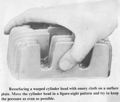
on a surface plate coated with red lead or machinist's bluing. Resurface the
cylinder head by lightly rubbing the gasket surface on plate glass covered with
a piece of #200 and then #400-grit emery cloth. Check the gasket surface of the
cylinder for warping by coating the repaired cylinder head with machinist's
bluing and lightly rubbing it over the gasket surface of the cylinder. Resurface
the gasket surface of the cylinder in the same manner as the head. Inspect the
cylinder base surface for nicks or burrs which would interfere with a good
gasket seal at this critical joint.
CYLINDER BORE
Inspect the cylinder bore for scoring caused by piston seizure or localized wear
in front of the transfer ports. NOTE: Localized wear between the transfer and
exhaust ports has three possible causes: (a) Failure to chamfer these port edges
after reboring causes the rings to bounce off the sharp port edges and spring
back against the cylinder bore. (b) Rings which fail to seat will lose tension
from reduced heat transfer and will bounce off the ports, and then rebound
against the cylinder bore. (c) Insufficient ring end gap will cause the rings to
expand and butt when the engine warms up.
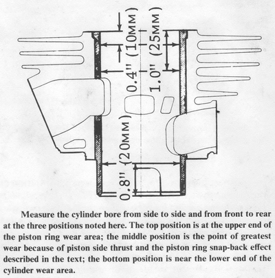
Use an inside micrometer to measure the cylinder bore from front to back and
from side to side at the three positions in the bore, as shown. Subtract the
largest dimension from the smallest to obtain the bore taper. NOTE: If the
cylinder is not worn out of round, the following method can be used to determine
bore taper without a micrometer. Insert a piston ring into the cylinder, using
the piston to keep it square in the bore. Measure the ring end gap with feeler
gauges at the three positions shown. Subtract the largest end gap from the
smallest, and then divide this circumferential taper by 3.14 (pi) to obtain the
bore taper.
PISTONS AND RINGS
Inspect the piston for seizure and/or deformation of the piston crown or ring
grooves. NOTE: If the piston has seizure marks around the piston pin hole
bosses, it indicates overheating from lean fuel mixtures, retarded ignition
timing, overloading, or a spark plug with too hot a heat range. If seized on the
front (exhaust) side of the skirt, the cause is excessive carbon deposits in the
exhaust port and combustion chamber, or use of low-quality oil or fuel with too
low an octane rating. Seizure on the rear of the piston skirt indicates an
overrich fuel mixture that washed the lubricant off the cylinder wall. Pitting
of the piston crown is caused by preignition from the use of low-octane
gasoline, ignition timing too far advanced, too hot a spark plug, excessive
combustion chamber deposits, or lean fuel mixtures. Collapsed ring grooves are
caused by detonation from excessive carbon deposits or local hot spots in the
combustion chamber, or by the piston striking the cylinder head. A hole melted
through the piston crown indicates too hot or too long a spark plug (which
protrudes into the combustion chamber), too lean a fuel mixture, or retarded
ignition timing.
The extent of brown coloring below the piston ring grooves indicates the degree
of blow-by. If the piston skirt is nearly black, this points to an overrich fuel
or oil mixture. Minor defects in the piston skirt can be corrected by light
sanding with #200-grit emery cloth. If there are scores in the piston skirt,
inspect the cylinder for matching defects.
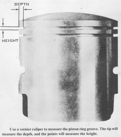
Inspect the piston ring lands for cracking or deformation, then check the ring
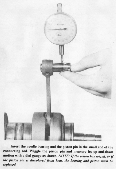
grooves for stepping caused by loose rings. Insert the wrist pin into the piston
and check the fit. Inspect the wrist pin and connecting rod needle bearings for
bluing or discoloration, indicating excessive heat. CAUTION: Replace the
wrist pin and needle bearings any time a piston seizure is evident, because the
excessive heat has been transferred to these parts, weakening them.
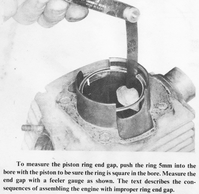
Push each piston ring into the cylinder bore with the piston to just above the
intake port. Measure the end gap with a feeler gauge. If the gap is too small,
rub both ends against a file held in a vise. CAUTION: Insufficient ring end
gap causes butting of the rings when the engine is hot, resulting in ring
breakage, accelerated cylinder wear, and possible ring seizure. Excessive ring
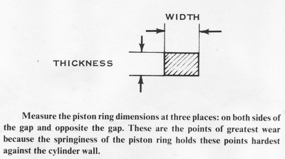
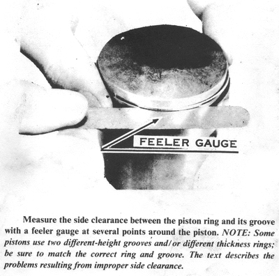
end gap detracts from engine performance and fuel economy. Check the piston
ring side clearance with a feeler gauge. Excessive side clearance causes
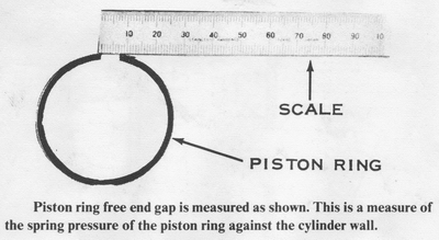
stepping of the ring grooves; inadequate clearance causes stuck rings. Measure
the free gap of used piston rings with a caliper to determine if they have lost
tension.
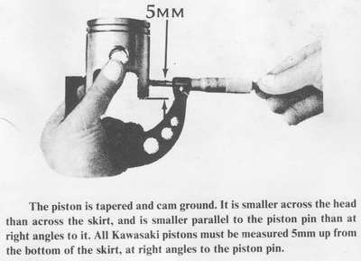
Use a micrometer to measure the piston diameter from front to back at the
specified height from the base of the skirt. This point on the skirt is not
necessarily the largest piston diameter, because the piston has a barrel profile
to reduce piston slap and friction. Subtract this measurement from the smallest
cylinder bore measurement to determine the amount of piston clearance. Compare
the piston clearance with the specification table to determine if a new piston
and/or cylinder rebore is required. NOTE: Another method of determining
whether the piston is too loose is to drop it into the cylinder, without piston
rings. The cylinder must be upside down on a flat surface to seal its upper end.
The piston should fall quickly, but slow down after it passes the exhaust port,
because the trapped air must escape past the piston skirt. If the piston drops
quickly, without noticeably slowing, it is too loose and should be replaced.
Replacement pistons and rings are available in standard size, or 0.020" (0.5mm)
and 0.040" (1.0mm) oversizes. Oversize pistons are marked "50" or "100" on the
piston crown for identification. Replacement pistons are sized to fit rebored
cylinders with normal clearance. However, it is wise to measure both the piston
and cylinder before assembly to make sure the piston clearance is within
specifications.
After boring, use a file or high-speed grinder to chamfer the transfer, exhaust,
and intake port edges to prevent piston ring breakage, ring noise, and premature
cylinder wear. Polish these chamfered edges with #400-grit emery cloth. Use a
hone with a reciprocating motion to put a crosshatch finish on the cylinder
walls. This improves the oil retention and hastens ring seating. Wash all parts
with soap and water before assembly to remove abrasives.
CRANKSHAFT
Don't disassemble the crankshaft. because it is pressed together and aligned at
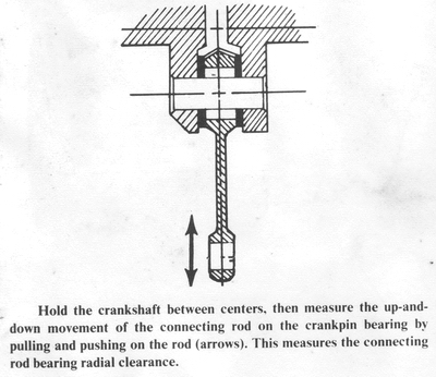
the factory. If worn, rebuilt crankshafts are available at reasonable cost. Move
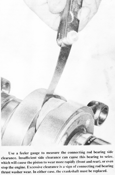
the connecting rod small end back and forth to check the big end bearings for
wear. If the connecting rod
side play is over 0.028", the crankpin bearing or thrust washers are worn and
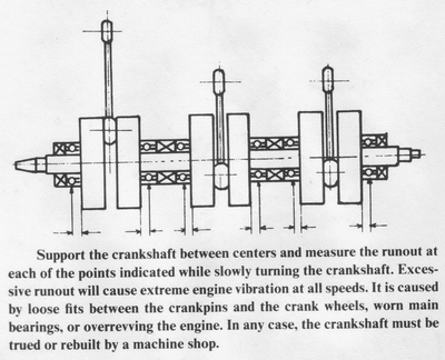
the crankshaft should be replaced. Support the crankshaft between centers or on
V-blocks, then measure the runout on each end of the shaft. If the ends have too
much runout, alignment is required. CAUTION: Excessive runout causes
vibration and accelerated main bearing wear.
CRANKCASES
Check the crankcase for hairline cracks or burrs on the gasket surfaces, which
would hinder oil and pressure sealing. Lay the mating surface of each case half
on a surface plate or plate glass coated with machinist's bluing to check for
warping. Minor repair can be made by lightly rubbing the surface on plate glass
covered with #200- and then #400-grit emery cloth. Use a figure-eight motion to
keep metal removal evenly distributed.
ASSEMBLING THE ENGINE
The first twenty-one steps of this procedure are for the H-series transmission
only. To assemble the S-series transmission, see Chapter 5, Clutch and
Transmission Service. From step twenty-two on, the instructions in this chapter
are for both H- and S-series engines, except where noted.
OUTPUT SHAFT
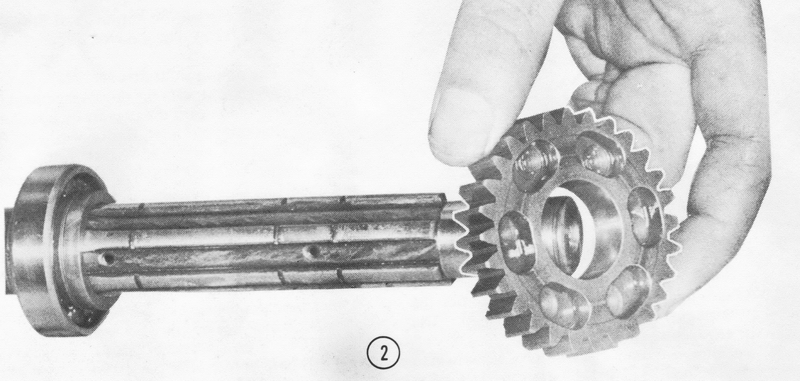
1) Slip the # 6005 bearing onto the long end of the output shaft. Seat it snugly
against the shoulder as shown. Add the proper thickness thrust washer based on
the clearance measurement procedure of the transmission adjustment section of
Chapter 5.
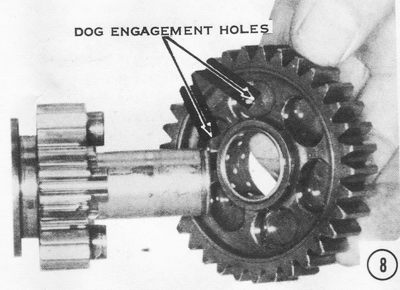
2) Install the output shaft second gear (28 teeth), with the dog engagement
holes facing away from the collar and bearing, as shown.
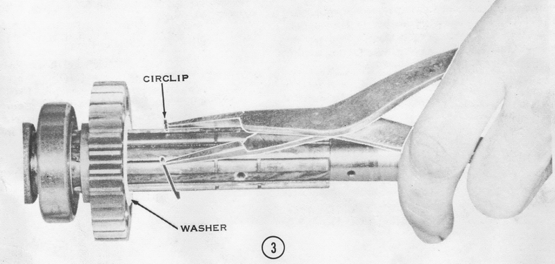
3) Slide on the proper thickness thrust washer, again based on the clearance
measurement procedure of the transmission adjustment section. Insert a circlip
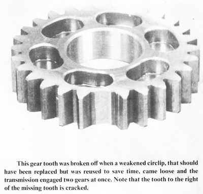
in the groove to hold the output shaft second gear in place. CAUTION: Be sure
the sharp edge of the circlip is facing away from the thrust washer. CAUTION:
Always use new circlips when assembling the transmission. Used circlips can lose
tension and be forced out of their grooves. This can allow the transmission to
go into two gears at once, causing extensive damage and loss of control from
rear wheel lockup.
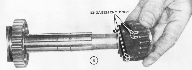
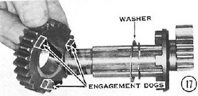
4) Next fit the output shaft fourth gear (23 teeth). The side of the gear with only three dogs on it goes on first. The other side of the gear has six dogs.
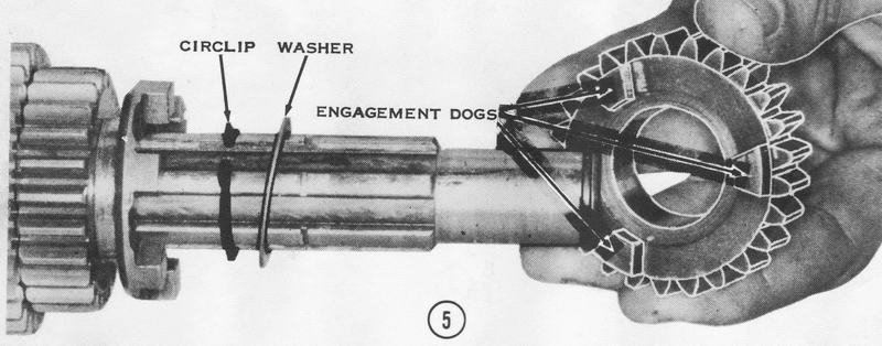
5) Fit another circlip to the groove closest to the gear just installed. This time the sharp edge of the circlip should face toward the output shaft fourth gear. Then put on a l.0mm-thick thrust washer. Next comes the output shaft third gear (H1: 25 teeth, H2: 20 teeth). The side with the engagement dogs goes on first.
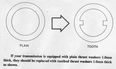
6) Put another 1.0mm-thick thrust washer next to the gear just installed. On all
H2's and on H1's, after engine number KAE-54101, this washer is toothed on the
inner edge. The teeth engage the splines on the shaft, preventing the washer
from spinning with the output shaft third gear. This toothed washer is
recommended for use in place of the plain steel washer in H1's under engine
number KAE-54101, if they have a tendency to jump out of third gear during
acceleration. Using circlip pliers, fit a circlip into the groove shown.
7) Next, slip on the output shaft fifth gear (H1: 21 teeth, H2: 17 teeth). The grooved side of the gear goes on first.
8) The output shaft first gear (H1: 33 teeth, H2: 26 teeth) goes on next, with the dog engagement hole side going on first and toward the previously installed gear.
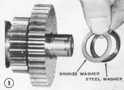
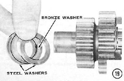
9) Put on the final thrust washers. On H1's through engine number KAE-54101, one phosphor bronze washer (slightly yellowish in color) goes on first and then one steel washer. Both washers are 1.0mm thick. On all H2's and on H1's from engine number KAE-54101 on, put on one phosphor-bronze washer followed by one 0.5mm- and one 1.0mm-thick steel washer. NOTE: If an H1 with an engine number less than KAE-54101 has a tendency to jump out of first gear, a 0.5mm steel washer may be added. Insert it between the phosphor bronze washer and the 1.0mm-thick steel washer. CAUTION: If the addition of this washer makes the output shaft hard to turn after the shaft has been installed in the upper engine case half, the washer must be removed, because the transmission is jumping out of first gear for some reason other than incorrect clearance. See the transmission inspection section of Chapter 5 for other suggested reasons.
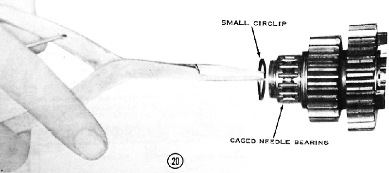
10) Next put on the caged needle bearing and secure it with a small-diameter circlip.
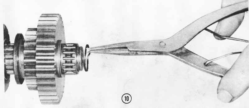
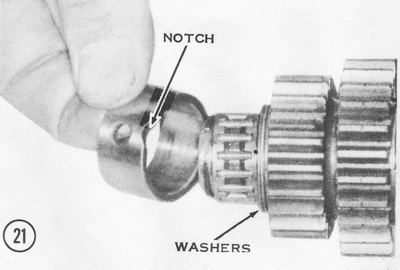
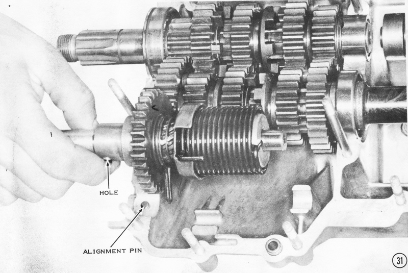
11) Slip on the bearing race, with the notched edge toward the washers installed in Step 9. NOTE: The hole in the race will fit on the alignment pin in the engine case half during engine assembly.
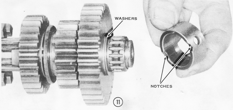
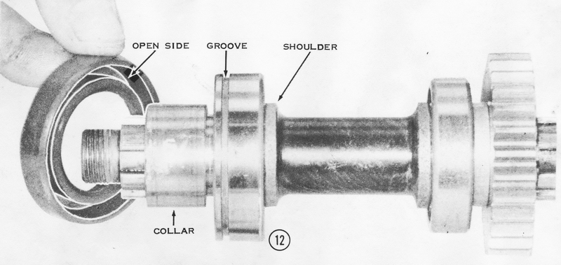
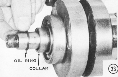
12) On the other end of the shaft, install the large ball bearing with the retaining groove away from the shoulder. NOTE: The H1 uses bearing number 6305N; the H2 uses bearing number 6205N. Slip on the collar and the oil seal. Be sure the "open" side of the seal is facing toward the bearing, as shown, or the transmission will leak oil.
DRIVESHAFT
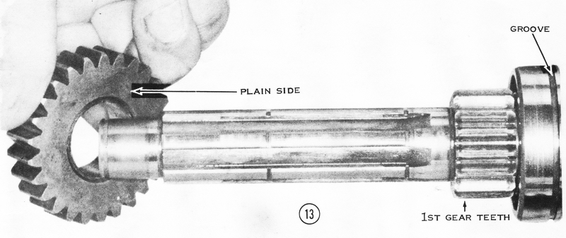
13) Install the large ball bearing (number 6205N) on the short end of the
driveshaft, with the locating groove facing away from the first-gear teeth
machined in the shaft. Slip the driveshaft fifth gear (H1: 26 teeth. H2: 21
teeth) onto the long end of the shaft, with the "plain" side facing toward the
first-gear teeth. NOTE: If the measurements taken of the driveshaft
fifth-to-third-gear clearance so indicate, a 0.5mm-thick washer should be put on
before the driveshaft fifth gear, and one after it before the circlip. If this
is the case, the 1.0mm-thick washer in Step 14 must not be installed.
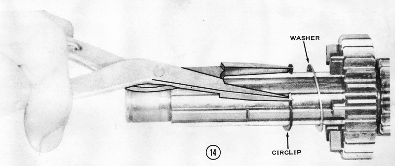
14) Put on one 1.0mm-thick steel thrust washer and secure the washer and the driveshaft fifth gear with a circlip in the groove closest to the gear. CAUTION.: Be sure the sharp edge of the circlip is facing away from the washer.
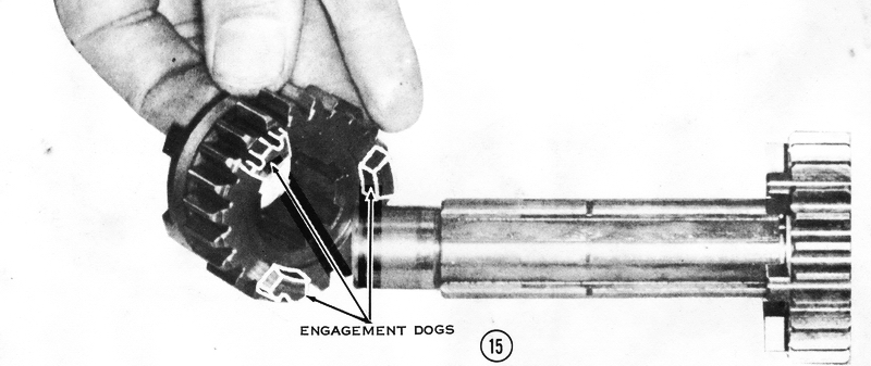
15) Slide the driveshaft third gear (H1: 23 teeth, H2: 18 teeth) onto the shaft. The side with three engagement dogs goes on first toward the driveshaft fifth gear.
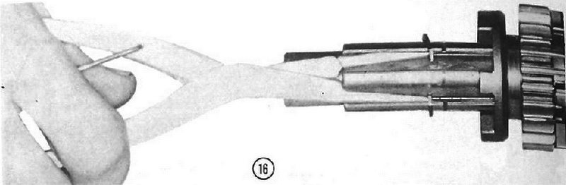
16) Install circlip in the last groove, with the sharp edge facing toward the gear installed in Step 15.
17) Slip a 1.0mm-thick washer onto the shaft, then install the driveshaft fourth gear (25 teeth). The side with the engagement dogs goes on first.
18) Now install the driveshaft second gear (H1: 20 teeth, H2: 19 teeth), so that the shoulder on one side of the gear faces toward the driveshaft fourth gear just installed in Step 17.

19) Second gear is followed by several thrust washers. On the H1, install one steel washer (1.0mm thick), one phosphor bronze washer (1.0mm thick), and one steel washer (1.0mm thick) in that order, as shown. On the H2, install one steel washer (1.0mm thick), one phosphor bronze washer (1.0mm thick), one steel washer (0.Smm thick), and one steel washer (1.0mm thick), in that order.
20) Slip on the caged needle bearing, and secure it with a small circlip.
21) Fit the outer race over the needle-bearing, with the notched edge facing the washers installed in Step 19.
KICK-START MECHANISM
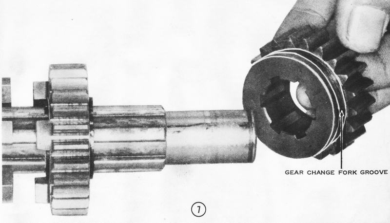
22) Spread the ends of the kickstarter gear holder and slip it into the groove
on the kickstarter gear. Slide
the kickstarter gear onto the splines on the kickstarter shaft so that the gear
holder faces away from the stop lever on the shaft.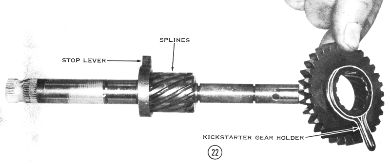
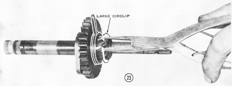
23) Using circlip pliers, install a large circlip in the groove at the end of
the splines.
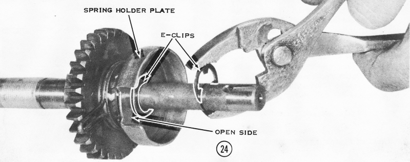
24) Put on the kickstarter spring holder plate, with the "open" side facing away from the kickstarter gear, as shown. Secure it in place with an E-clip and fit another E-clip to the remaining groove in the shaft.
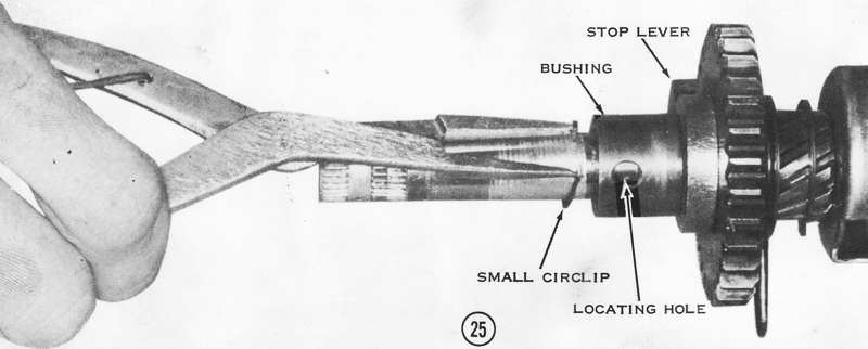
25) Slide the kickstarter shaft bushing onto the other end of the shaft so that the locating hole is farther from the stop lever. Fasten the bushing in place with a small circlip.
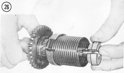
26) Put on the kickstarter spring so that the "hooked" end fits through the slot in the edge of the kickstarter spring holder plate. The other end fits into the hole through the end of the shaft. NOTE: Align the spring end in the hole as shown in the inset. Slip on the kickstarter spring guide so that the beveled edge is inside the spring.
ASSEMBLING THE CRANKCASE HALVES
27) Slide the shift drum partway into the upper crankcase half. Slip the three
shift forks onto the drum as shown. Notice that two of the forks are alike
except for the flycutting for first-gear clearance on one. The flycut fork goes
on first, with its flycut edge facing toward the crankcase wall. Screw in the
fork guide pins, each with a lock plate. Tighten the pins securely and bend up
the tabs on the lock plates as shown.
28) Push the shift drum as far into the case as it will go, and then install the drum retainer plate. NOTE: Stake the countersunk head screw in place with a center punch to prevent its loosening. CAUTION: Make sure the screws are tight; subsequent loosening of the plate lets the drum jump sideways, with consequent jumping out of gear, erratic shifting, and damage to the transmission. Install the spring anchor plate and tighten the screw securely. Hook the drum lever spring to the anchor plate and to the drum lever. Fasten the drum lever in place with the shoulder bolt. NOTE: Loc-Tite the shoulder bolt to prevent its loosening. CAUTION: Don't overtighten this bolt, and check the lever for binding, both of which result in erratic shifting or overshifting.
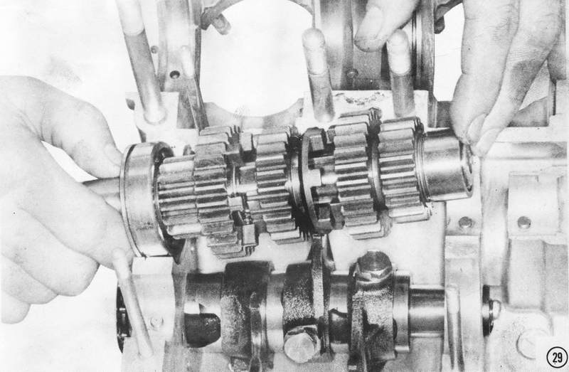
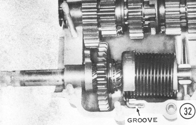
29) Position the driveshaft in the upper crankcase half. Be sure the bearing
ring fits into the groove in the ball bearing and the alignment pin fits into
the hole in the needle bearing outer race. CAUTION: If the half ring is left
out, clutch disengagement tension will force the input shaft to move in the
crankcase assembly. Eventually, this causes mis-shifting and interference
between the first output gear and the fourth input gear. One symptom of such
gear interference is a tendency of the motorcycle to "creep" in neutral, but
only with the clutch engaged. The center shift fork must fit into the groove
in the driveshaft third gear as shown.
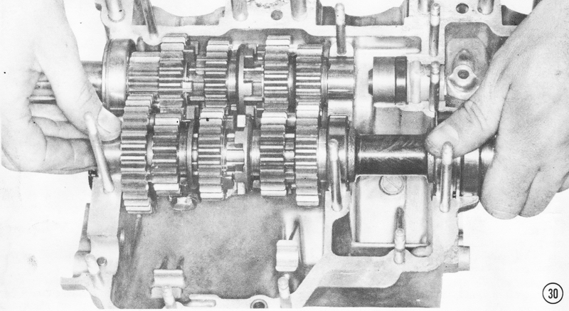
30) Install the output shaft in the upper crankcase half. The bearing retaining ring must fit into the groove in the ball bearing, and the aligning pin must fit into the hole in the needle bearing outer race. The other two shift forks fit into the grooves in the output shaft fourth and fifth gears. Install the clutch pushrod guide with the projection facing in as shown. The pushrod guide fits on an alignment pin. Then install the oil seal flat against the guide, with the marked side facing out.

TESTING THE TRANSMISSION SHIFTING SEQUENCE
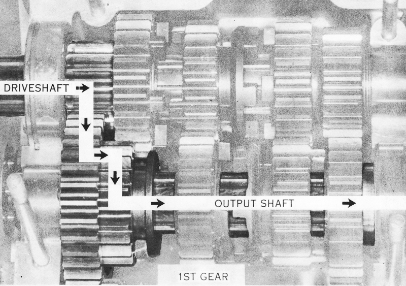
First Gear: Shift the transmission into each gear in turn to see that
they engage as fully as illustrated and that all the gears turn smoothly. In
first gear, the output shaft fifth gear moves over to engage the output shaft
first gear. The power path is from the driveshaft first gear, an integral part
of the driveshaft. to the output shaft fifth gear, splined to the output shaft.
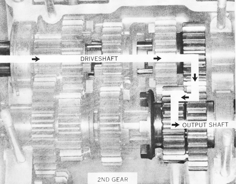
Second Gear: In second gear, the output shaft fifth gear moves back to
its neutral position and the output shaft fourth gear moves over to engage the
output shaft second gear. The driveshaft turns the driveshaft second gear, which
is splined to it. The driveshaft second gear meshes with the output shaft second
gear, and it drives the output shaft fourth gear through the engagement dogs.
The output shaft fourth gear is splined to the output shaft to turn it.
Third Gear: In third gear, the output shaft fourth gear moves back to
engage the output shaft third gear. The power flows from the driveshaft to the
driveshaft third gear, which is splined to it. The driveshaft third gear drives
the output shaft third gear, which turns the output shaft fourth gear through
its dogs. The output shaft fourth gear is splined to the output shaft.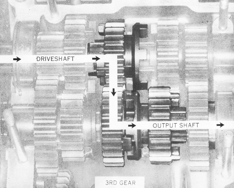
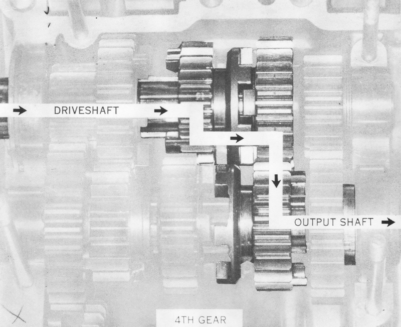
Fourth Gear: In fourth gear. the output shaft fourth gear returns to its
neutral position, and the driveshaft third gear moves over to engage the
driveshaft fourth gear. The driveshaft turns the driveshaft third gear, which is
splined to it. The driveshaft third gear turns the driveshaft fourth gear
through its dogs. The driveshaft fourth gear meshes with the output shaft fourth
gear, which is splined to the output shaft to turn it.
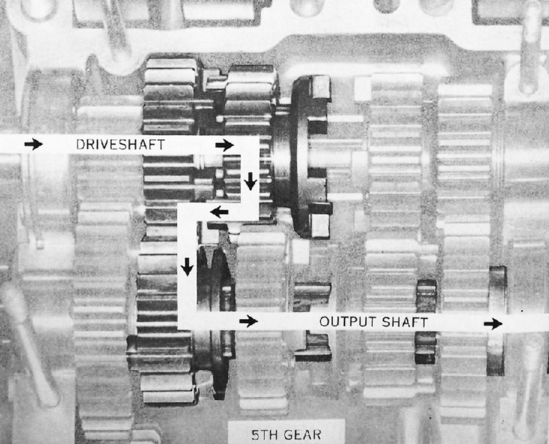
Fifth Gear: In fifth gear, the driveshaft third gear moves the other way
to engage the dogs on the driveshaft fifth gear. The power flow now is as
follows: the driveshaft turns the driveshaft third gear through its splines.
This gear turns the driveshaft fifth gear through its engagement dogs. The
driveshaft fifth gear meshes with the output shaft fifth gear, which is splined
to the output shaft. Before continuing the assembly, return the transmission to
neutral.
31) Install the kickstarter shaft so that the end of the gear holder fits into
the groove in the upper case half,
and the alignment pin fits into the hole in the bushing, as shown.
32) The hook on the kickstarter return spring must go into the groove in the
upper case half.
33) Install the collar with the chamfered edge away from the bearing. Slip the
O-ring seal (H1 : 22mm, H2: 24mm, S-series: 18mm) onto the drive (threaded) end
of the crankshaft. NOTE: This O-ring, must be in good condition or the
right-hand crankcase could leak, causing seizure.
34) Slide the crankshaft and seals into place. The H1 uses seal number TC326210 on the drive (threaded) end of the crank and number TC255210 on the alternator (tapered) end. The H2 uses number TCY36729 on the drive end and TCY306210 on the alternator end. The S-series engines use seal number TC326210 on the drive end and TCY256210 on the alternator end. NOTE: The notched side of the seal must face the bearing in all cases. Otherwise, the crankshaft bearing and the connecting rod bearing will not be lubricated sufficiently and will fail.
35) Carefully lower the crankshaft into the upper crankcase half. The bearing
alignment ring must fit into the groove in the third crankshaft bearing as
shown.
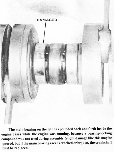
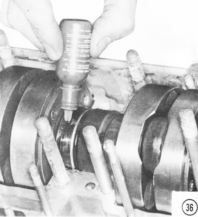
36) Apply a little Kawasaki Super Lock or retaining compound such as Loctite 609 to each bearing race. This will prevent
the bearings from "working" in the cases while the engine is running.
CAUTION:
Keep the adhesive away from the oil holes; blocked oil channels result in engine
failure. Only a trace is required. Applying too much adhesive can
result in bearing failure.
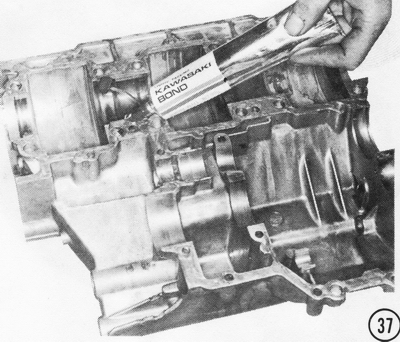
37) Apply a thin, even coat of Kawasaki Bond to the mating surface of the lower
crankcase half. NOTE: The mating surface must be as clean as possible. Remove
all of the old sealant before applying the new sealant.
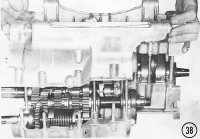
38) Make sure the crankcase joint faces are free of washers or other objects,
then lower the lower crankcase half into place on the upper crankcase half.
Press it down firmly. Check these items before assembling the crankcase:
Kickstarter: bushing on pin, holder in groove, spring hook in groove. Oil seals:
pushed in flush against the adjacent bearings. Bearing outer races: small-pins
engaged. large-half rings engaged. NOTE: One of the common causes of unnecessary
damage and extra work is caused by assembling the crankcase with the bearing
pins and rings misaligned. Seat the bottom case half with a rubber mallet.
CAUTION: Don't use force to overcome the gap at the crankcase joint; instead,
remove the bottom case half and correct any obstruction. Clean and reapply
sealant to the case mating surfaces.
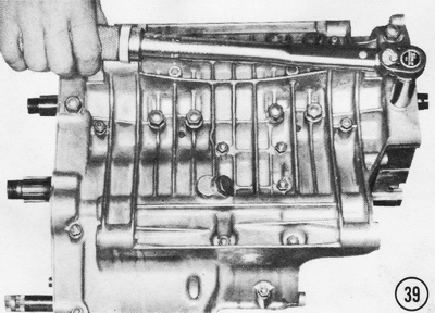
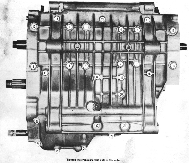
39) Install the 12 large 10mm nuts, each with a lockwasher. Put on the 15 small
6mm nuts, each with a
lockwasher. Using a torque wrench and following the tightening sequence shown,
tighten the large nuts to 23 ft-lbs. of torque, and then tighten the small nuts
to 5 ft-lbs. CAUTION: Clear the drain holes of any sealant blockage; these holes
must be open to allow any fuel overflow or water to drain out of the "valley" in
the top of the crankcase.
FITTING THE ENGINE TO THE FRAME
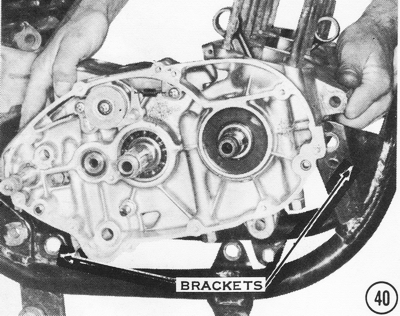
40) Before assembling the engine further, install it in the frame. It is much
lighter and easier to handle now than when it is fully assembled. From the left
side, slip the engine into the frame, then insert the mounting bolts into the
mounting brackets. Put the lockwashers and nuts onto the mounting bolts, but do
not tighten them.
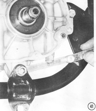
41) Measure the clearance between the mounting brackets on the frame and the
mounting lugs on the engine, as shown, on both sides, at all three of the lower
engine mounting points.
42) Insert a shim of the proper thickness in the gap measured in the previous
step. Shims of the following thicknesses are available: 0.5, 0.8, 1.0, 1.6, 2.0,
and 2.3mm. For ease of installation, order only "rear" shims; they are 18mm
longer, making them much easier to handle. NOTE: Shims were installed at the
factory starting with the 1974 model HI frame # HI F-00001. All HI frame numbers
starting with "KAF" are for 1969-1973 models. Installation in H2's started xlth
frame H2F-09082, and on S2's from frame #S2-26858. All SI's have the shims
installed by the factory. Even if your machine does not have these shims, they
should be installed to keep engine vibration to a minimum. Without these shims,
the frame brackets take a "set" after the mounting bolts are tightened, allowing
the engine to loosen in the frame. This can aggravate engine vibration to the
point of rider discomfort. It can even break the engine mount frame brackets in
some cases.
43) Install the upper rear mounting bracket and tighten all the mounting bolt
nuts to 25 ft-lbs. of torque. On S-series machines and H2's, tighten the small
mount bracket bolts at the front of the engine to 15 ft-lbs. of torque.
ASSEMBLING THE RIGHT-HAND SIDE OF THE ENGINE
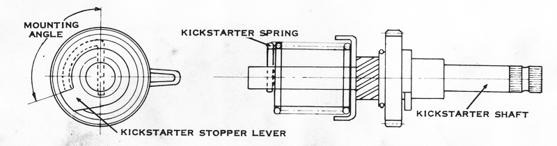
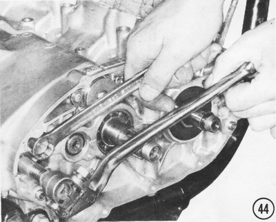
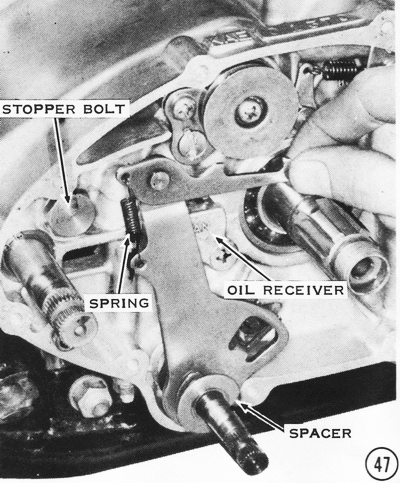
44) Temporarily mount the kickstarter lever on the kickstarter shaft. Turn the
shaft 150°, or almost one-half turn, counterclockwise, and hold it there. Insert
the kickstarter stop bolt, and then tighten it securely. Check that the
kickstarter lever returns in a clockwise direction after it has been pushed
counterclockwise. If it does not return properly, the return spring has been
mounted improperly and the cases must be split again. See Step 26 in the engine
assembly section above.
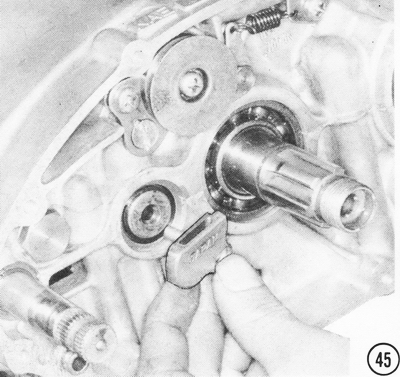
45) Install the oil receiver into the end of the output shaft, and secure it
with a countersunk head screw 16mm long. Tighten the screw securely. CAUTION: If
the screw is too long, it will pass through the case and touch 1st gear, which
could lock the transmission.
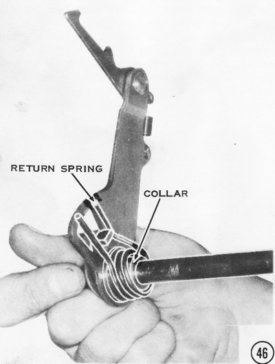
46) Install the gear-change lever collar and the gear-change lever return
spring. NOTE: On early Hl 's and on S-series models, the collar is integral with
the lever. CAUTION: The flat side of the spring must be toward the lever as
shown, or the lever will bind.
47) Slide the gear-change lever shaft into the lower engine case so that the
return spring straddles the return spring pin. Hook the ratchet mechanism onto
the end of the gear-change drum. NOTE: Be sure the ends of the ratchet mechanism
spring are turned toward the inside. Otherwise they might catch on the back of
the clutch during engine operation and be pulled loose from the ratchet
mechanism, making gear changes impossible. Slip the gear-change lever spacer
onto the end of the gear-change lever shaft as shown. NOTE: The S-series models
do not have this spacer.
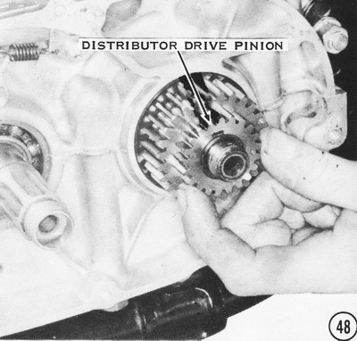
48) Press the Woodruff key into the keyway in the drive end of the crankshaft.
Slip the primary pinion onto the end of the shaft. H1's below engine number
KAE-54101 also have a distributor drive pinion, as shown. Later H1's have a
plain collar in place of this gear. H2's and S-series engines have a shorter
shaft end that needs neither the gear nor the collar.
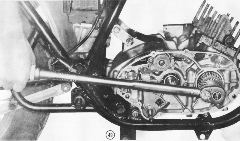
49) Install the lock plate with the tang into the keyway slot, and then screw on
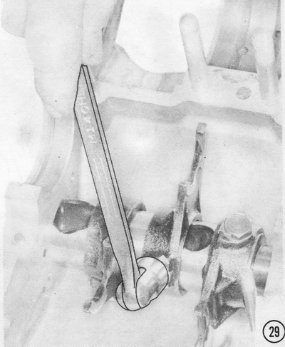
the primary pinion nut, with the flat side facing in. Insert a connecting rod
retaining plate under the small end of the connecting rod of
the right-hand cylinder, and then tighten the primary pinion nut to 85 ft-lbs.
of torque.
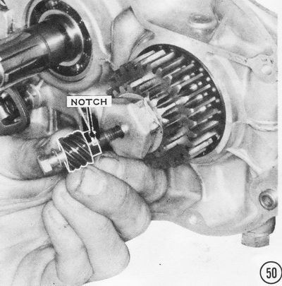
50) Bend up the edge of the primary pinion nut lock plate. Fit the oil pump
pinion lock plate as shown. Slip on the oil pump pinion so that the tab on the
lock plate fits into the notch in the pinion. NOTE: Early 1969 H1's do not have
an oil pump pinion lock plate, and there is no notch for the lock plate tab in
the pinion. In this case, the oil pump pinion bolt should be treated with a
locking compound such as Kawasaki Liquid Lock-K or an equivalent to prevent the
bolt's coming loose. CAUTION: If the bolt comes loose, the tachometer and the
oil pump will stop working; stop immediately, as major engine damage is imminent
from oil starvation. Insert the oil pump pinion bolt with a star washer and
tighten it to 5 ft-lbs. of torque.
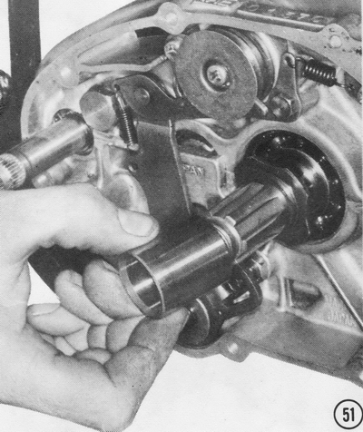
51) Slip the clutch housing inner thrust washer onto the end of the driveshaft.
Then install the clutch bushing as shown.
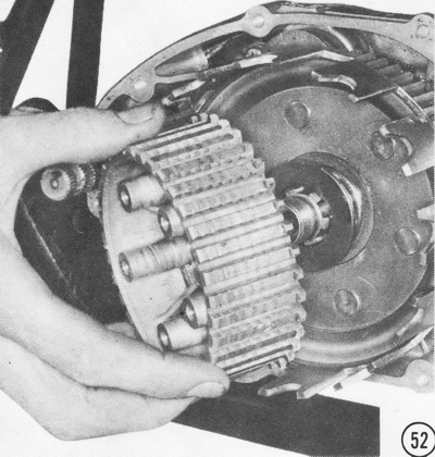
52) Slide the clutch housing into place on the clutch bushing so that the gear teeth on the back of the housing mesh with the teeth of the primary pinion. In stall the clutch housing outer washer and the clutch hub as shown.
53) Install the clutch hub nut lock plate, with the tang in the hole near the center of the hub, and then screw on the clutch hub nut, flat side facing in. Tighten the nut to 85 ft-lbs. of torque on H-series machines and to 70 ft-lbs. on S-series engines. Bend up the edge of the lock plate to prevent the nut from loosening during engine operation. Check that the hub turns freely without excessive play.
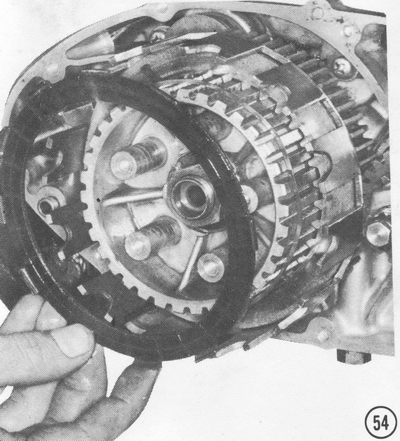
54) Install one separator ring and one friction plate. The tabs on the plate fit between the "fingers'' on the clutch housing. NOTE: On H1 's, the metal tabs of the friction plates "hook " outward.
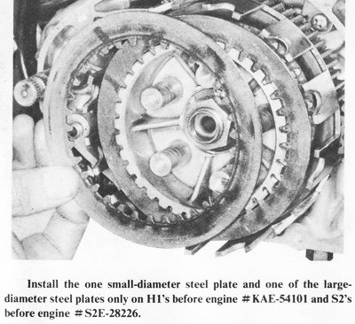
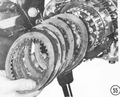
55) Install the rest of the steel and friction plates alternately, with a
separator ring inside each friction plate. NOTE: On the H2 one friction plate
has shorter tabs. This plate must be the sixth friction plate installed. Its
shorter tabs clear the clutch housing holder ring, which is installed at the
same time. On H1's before engine number KAE-54101 and S2's before engine number
S2E-28226,
the last plate is a steel one. All others have a friction plate on the outside.
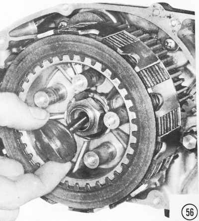
56) Slip the clutch spring plate pusher into the hole in the driveshaft. NOTE:
On H2's, put the 5/16-inch steel ball into the hole first.
57) To install the clutch spring plate on early H1's, before engine number KAE-54101. replace the clutch spring guides and the clutch springs, and then fasten them in place with the five bolts and flat washers. Tighten the bolts evenly in a criss-cross pattern to 5 ft-lbs. of torque. NOTE: These bolts must be 18mm long. If they are too long the springs will not be compressed all the way and the clutch can slip. The bolts can also hit the engine cover. If they are too short, the clutch will drag and the spring coils will bind.
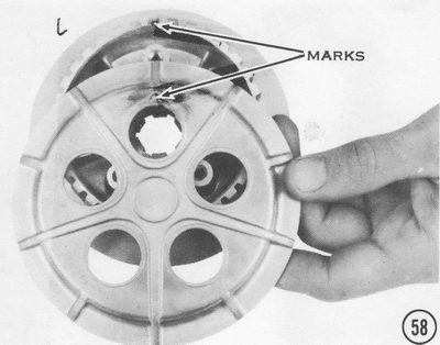
58) To install the clutch spring plate on all models, except H1's before
number KAE-54101, align it as shown. NOTE: The splines inside the spring plate
fit the splines on the clutch hub so that the spring holes line up only in one
position. Insert the spring guides (H-series only) and the clutch springs, and
then fasten them in place with the five bolts and flat washers. Tighten the
bolts evenly in a criss-cross pattern to 5 ft-lbs. of torque on H-series models
and to 3 ft-lbs. of torque on S-series models.
RIGHT-HAND ENGINE COVER-H-SERIES ONLY
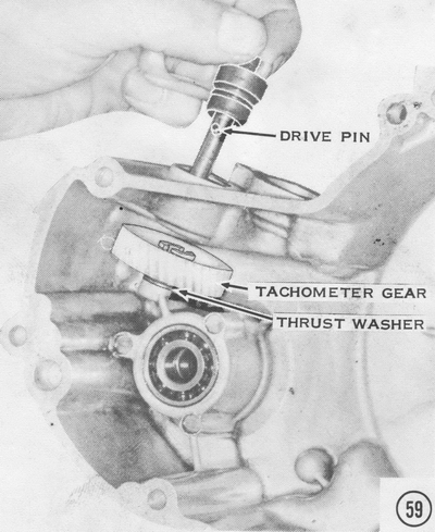
59) On H-series models, position the tachometer gear in the right-hand engine
cover with one small thrust washer beneath it as shown. Slip the tachometer gear
shaft, with the drive pin in place, through the engine cover and the tachometer
gear so that the drive pin fits into the slot in the top of the gear. NOTE: Be
sure the 0-ring is in place.
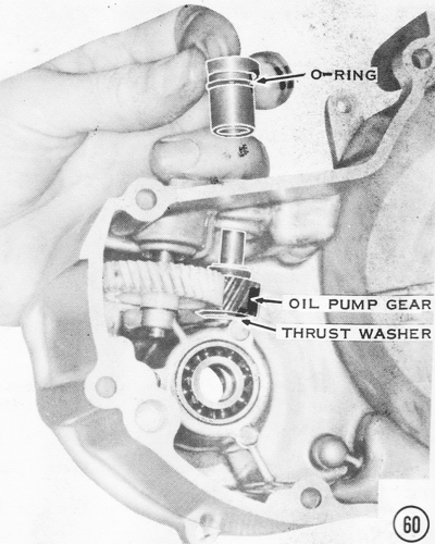
60) Slip the oil pump gear into place with one small thrust washer under it. Push the oil pump gear bushing down over the end of the gear shaft to locate it in the engine cover. CAUTION: Make sure the 0-ring is in place.
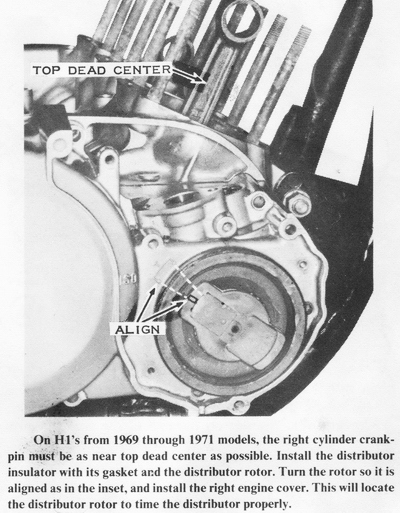
61) For H1 models from 1969 through 1971, insert the distributor shaft from the outside of the cover through the ball bearing. and then push the drive pin into the hole in the inside end of the shaft. Place the distributor drive gear on the end of the distributor shaft, with the shoulder facing toward the bearing as shown, so that the slot in the shoulder engages the pin in the shaft. Secure the gear with a washer, lockwasher, and a 6mm nut.
RIGHT-HAND ENGINE COVER-S-SERIES ONLY
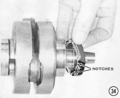
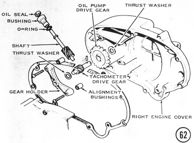
62) To assemble the S-series right engine cover, position the oil pump gear in
the cover with a large thrust washer behind it. Slip the tachometer drive gear,
with the drive pin installed, into the oil pump drive gear so that the drive pin
engages the notches in the face of the oil pump drive gear. Put on the other
small thrust washer and mount the tachometer gear holder on the alignment dowel
bushings as shown. Assemble the tachometer gear shaft bushing, with the oil seal
and O-ring, onto the tachometer gear shaft, and then push the assembly into the
hole in the front of the right engine cover so that the tachometer gears mesh.
ALL MODELS
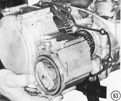
63) Stick the gasket onto the edge of the crankcase with heavy grease and put
the right engine cover into place while slowly turning the crankshaft to allow
the gears to mesh.
64) Be sure the gasket is in good condition and then install the oil pump. Use lockwashers under the screw heads and tighten them securely. CAUTION: Make sure that the flat on the end of the shaft fits the notch in the oil pump drive gear shaft. On S-series models, install the oil pump cable holder above the oil pump with two Phillips-head screws.
NOTE: The oil pump, lines, and check valves may be checked for proper operation prior to assembly by driving the pump shaft CCW with a drill motor.
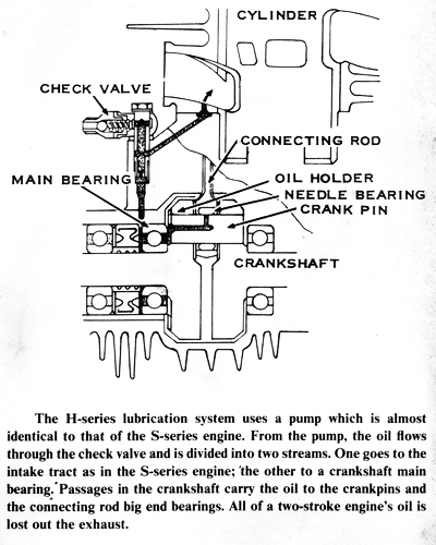
Check valves are used on the oil lines to prevent cylinder blowback against oil flow and to seal the line when the pump is not operating to prevent oil from draining into the cylinder. Cracking pressure for the valve should be 4.3 - 4.6 psi.
Check valves used on earlier models can be easily disassembled for inspection and cleaning. Ball seat should be smooth and free of deposits. Weak springs may be stretched in small increments to attain desired cracking pressure.
Note: The small end of the spring must be positioned against the ball when reassembled.
Check valves used on later models do not have hex fitting and are not designed for easy disassembly. Cleaning of this type valve is limited to soaking in a cleaner to dissolve deposits.
Caution: Never blow through lines with compressed air. It can permanently damage the valve.
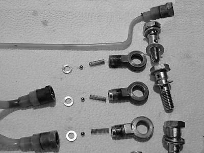
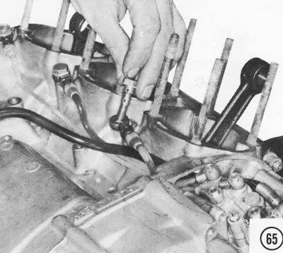
65) Install the intake oil line first, then the output oil lines. Be sure there
are aluminum washers on both sides of each banjo fitting. On motorcycles with
engine numbers S1E-10965, S2E-41105, H1E-83625, H2E-30126 and up, and on all
S3's, a three-way washer that has bend-up tabs to lock the banjo bolts in place
is used on top of the banjo fittings. The check valve bolts use two
different-sized gaskets. The gasket below the check valve has an 8.5mm inside
diameter; the gasket above the check valve has a 10mm inside diameter.
NOTE: Oil leaks may be prevented by using Stat-o-seals on each side of the
oil line banjo fittings in place of the aluminum washers and top lock plate.
66) Feed the oil pump control cable through the oil line hole in the oil pump chamber. NOTE: The oil pump cable is the longest of the four cables coming from the] unction box on the cable from the twistgrip. Push the cable through the adjuster in the cable holder tab as shown, and then fit the cable nipple into the tang on the oil pump control lever. Bend the tang over to hold the cable nipple firmly.
67) Fasten the oil pump lever cover in place with two short screws. CAUTION: Do not overtighten them, or the plastic lever cover may break. Position the distributor cap with its gasket and high-tension wiring as shown, and then fasten the cap in place with the two clips. Tighten these screws securely. The rubber wiring grommet snaps into place on the engine case. NOTE: H1's after engine number KAE-54101, and H2's and S-series units do not have a distributor cap and its high-tension wiring.
ASSEMBLING THE LEFT-HAND SIDE OF THE ENGINE
68) Position the engine sprocket on the splines of
the output shaft. The side with the shoulder goes on first. Fasten it in place
with a lock plate and a nut, flat side facing in. The tab on the lock plate fits
into the hole in the sprocket. Tighten the nut to 85 ft-lbs. of torque. Fold up
the edge of the lock tab with a chisel. CAUTION: If the sprocket is installed
with the shoulder on the outside, the drive chain cannot be aligned properly. If
the machine has an endless chain (H1 frame number H1F-00001 and up, and all
H2's), first slip the sprocket inside the chain before putting it onto the end
of the output shaft. CAUTION: The endless chain cannot be looped over the engine
sprocket after the sprocket is mounted on the output shaft. There is too little
room inside the frame to get the chain outside the sprocket.
69) Slide the clutch pushrods into the hole in the driveshaft, the long rod
first and then the short one.
70) Slip the clutch release mechanism into the hole in the engine case so that
the lever is to the left as shown. Fasten it in place with two countersunk head
screws. Tighten them securely.

71) Insert the clutch cable through the hole in the
case, and then slip the cable nipple into the slot in the cable holder as
shown. Fold up the tang in the cable holder so the nipple cannot slip out.
Adjust the clutch as discussed in the next chapter, on clutch and transmission
service.
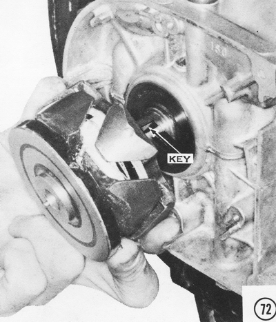
72) Push the Woodruff key into the slot in the crankshaft and then mount the
alternator rotor so that the slot fits onto the key. CAUTION: Be sure there are
no pieces of metal stuck to the rotor, inside or out. Debris in the alternator
could damage it during engine operation. NOTE: For S-series and H1B ignition
assembly, see the Ignition System section of Chapter 7, Electrical System Service.
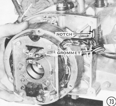
73) Position the stator over the rotor as shown. On some models, part of the
alternator cover is integral with the stator. CAUTION: Be sure the wiring
grommet fits into the notch in the case or it will be pinched. Inspect the
inside of the stator for pieces of metal stuck to the coils.
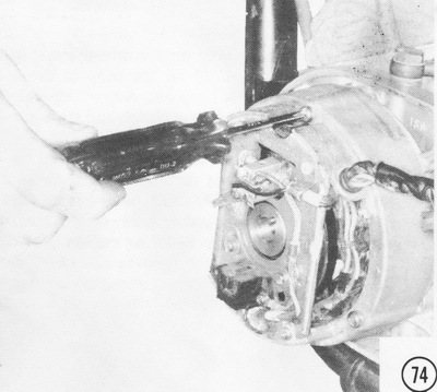
74) Fasten
the stator firmly in place with three screws and lockwashers on H1 models from
1969 through 1971. On H2's and later H1's, do not use lockwashers, because they
would mar the finish of the cover.
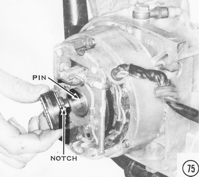
75) Install the signal generator rotor in the alternator rotor so that the pin
fits into the notch.
76) Fasten the rotors in place with a long bolt and lockwasher. Tighten the bolt
to 13 ft-lbs. of torque. Use a connecting rod retaining plate to prevent the
crankshaft from turning.
77) Fit the alternator cover in place and fasten it securely. On later models,
install the ignition cover with a gasket.
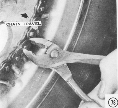
78) Put the drive chain over the two sprockets and join the ends with the master
link. CAUTION: The clip must be mounted as shown, with the open side facing away
from the direction of chain travel. This prevents the open end from catching on
the chain guard or other parts of the motorcycle and being forced off the chain.
A master link failure on the road can mean a long walk at best or broken engine
cases at worst. CAUTION: Be sure the clip is firmly seated in the grooves.
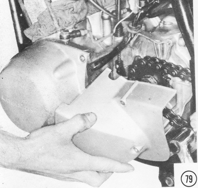
79) Install the sprocket cover. CAUTION: Be sure the wiring grommets fit into
the notches in the covers and the wire loom is short enough that it doesn't
touch the chain on the engine sprocket.
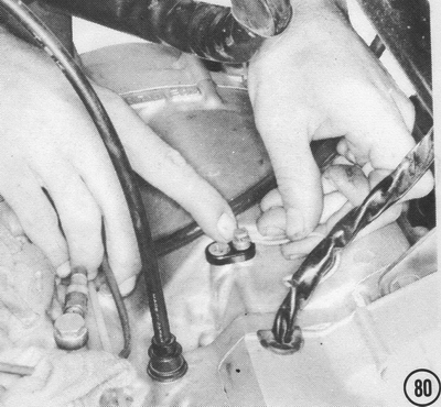
80) Install the neutral switch and tighten the screw securely. Connect the green
neutral switch wire by pushing down the spring-loaded collar and inserting the
bare end of the wire into the hole.
ASSEMBLING THE TOP END OF THE ENGINE, AND FINAL ASSEMBLY
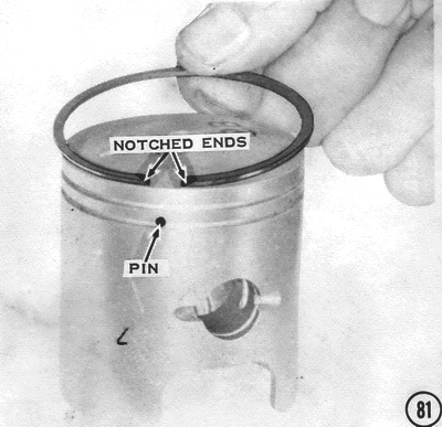
81) Install a spring steel expander ring in the bottom ring groove so that its
ends fit the locating pin. NOTE: The S-series models do not use this type of
ring. Spread each piston ring slightly, and then slip it over the top of the
piston and into the groove. The cutaways on the ends of the rings fit the
locating pins in the ring grooves. Install the bottom, all-black ring first. The
top ring has a shiny chrome outer edge.
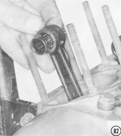
82) Slip the small end needle bearing inside the connecting rod eye as shown.
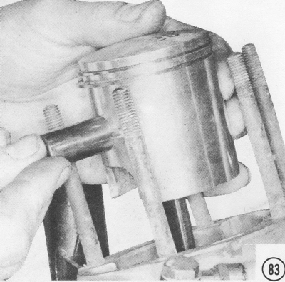
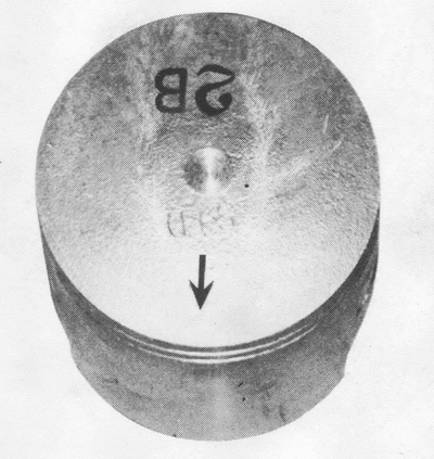
83) Install one new circlip before putting the piston on the connecting rod. The
gap must be on the bottom or the top. CAUTION: If the gap is at the sides, the
circlip will be compressed by the inertial forces of the piston changing
direction at the top and bottom of its stroke. A loose circlip inside a running
engine can completely destroy it in seconds! Also, be careful not to distort the
circlip too much while installing it, as this can cause it to lose tension and
fall out. Hold the piston in place over the small end of the connecting rod with
the arrow pointing forward as shown in the inset. Install the piston pin.
84) Install another new piston pin circlip with the gap at the bottom or the
top. NOTE: A rag stuffed under the piston prevents losing a circlip into the
crankcase during assembly. CAUTION: If a circlip falls into the crankcase, it
must be removed before going any further. Repeat steps 81 through 84 in that
order for the center and right pistons.

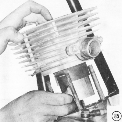
85) Put a cylinder base gasket over the cylinder hold-down studs. Be sure the
cutouts for the transfer ports match the crankcase. CAUTION: H-series models
have an oil passage from the crankcase to the cylinder. The hole in the gasket
must coincide with this hole. At the same time, check H2 cylinders to be sure
the oil jet in the hole is clear. Oil the inside of the cylinder bore and. while
compressing the rings with the fingers, slip the cylinder down over the piston
and into the crankcase.
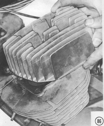
86) Position a new head gasket on top of each cylinder, and then install the cylinder heads. Fasten each with four sleeve nuts. Each sleeve nut has a lockwasher and a flat washer. CAUTION: Be sure the flat washer rests on the cylinder head, or the aluminum head would be severely scarred by the lockwasher.
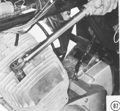
87) Torque the head nuts of all models except the H2 to 16 ft-lbs. of torque.
The H2 needs 30 ft-lbs. Install the spark plugs and push the spark plug leads
into place. Each lead is marked "L," "C," or "R" for its cylinder position.
NOTE: See the specifications section of Chapter 7, Electrical System Service,
for spark plug type and gap.
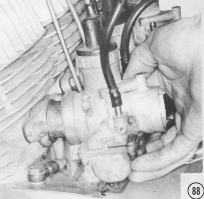
88) If the intake manifolds have been removed, remount them. NOTE: The thick gasket is a heat insulator. It must be used to keep the carburetors cool. Sort the carburetors to be sure of matching them to the correct cylinder. On H-series models, the carburetor with the vacuum fitting goes on the right cylinder; the other two are identical. On the S1, the left carburetor has the air screw on the left; the other two are identical. On the S2 and S3, the right and center carburetors are the same, with their throttle stop screws and air screws to the right. Push the carburetors onto the manifolds and tighten the clamps securely. Sight across the float bowl flanges to check that the carburetors are all properly aligned. CAUTION: If the engine is run with these clamps loose, the carburetors can vibrate excessively, which pounds the phenolic bushing inside the carburetor clamp section out of shape. After this happens, the joint between the carburetor and the manifold can leak air, leaning the mixture and causing engine overheating and possibly seizure.
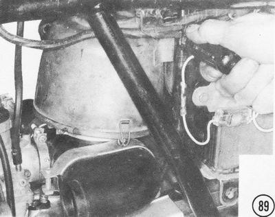
89) Mount the air cleaner with one long screw as shown. Slip the rubber air duct
into place on the carburetors and the air cleaner, and then tighten all the
clamps securely. CAUTION: On S-series models, be sure the ends of the ducts are
properly seated in the air cleaner housing. If the air cleaner intake has a
silencer horn on it, mount it at this time.
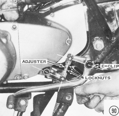
90) Grease the shift lever pivot. and then mount the shift lever. The clamp bolt
must be removed. Be sure to match the S-bend in the linkages shown here. If the
linkage is assembled in a U-shape, the transmission will shift backward with
neutral at the top and fifth at the bottom. Tighten the lever clamp bolt
securely, and then fasten the pedal in place on the pivot with a washer and an
E-clip. NOTE: The S-series models and the H2 use the, left footpeg bolt as a
pedal pivot. The H1 after frame number H1F-00001 has a separate bolt for the
pedal pivot. Fasten the S-series and H2 pivot bolt. with the left footpeg in
place, with a 12mm nut on the other side of the frame gusset. The H1 bolt
doesn't need a nut. Tighten the pivot bolt to 40 ft-lbs. of torque. Loosen the
two locknuts on the shift linkage adjuster. CAUTION: On H-series models, the
locknut on the engine end of the adjuster has a left-hand thread. It turns
opposite to the normal rotation for loosening. On S-series models, the nut
nearest the shift pedal lever has a left-hand thread. Turn the adjuster so that
the pedal is at the same height as the top of the footpeg, then tighten both
locknuts securely.
91) Mount the mufflers going from left to right. Fasten the header pipes to the cylinders using new gaskets and new lockwashers: Do not tighten the nuts yet. NOTE: The gaskets are compressed in use and will not seal well if reused. The intense heat of the exhaust causes the lockwashers to lose their "spring, " and they will not hold well if used for long periods or if reused. Slip each muffler into place. Start the bolts into the front muffler mounts, but do not tighten them yet. Fasten each muffler at the rear with the passenger footpeg bolts and tighten the front muffler mount bolts. Tighten the header pipe flange nuts to 5 ft-lbs. of torque on the H1, and to 12 ft-lbs. on the S-series models and the H2. NOTE: The H1 has a smaller stud size than the S-series models and the H2. If an exhaust flange stud should break on an H1, it must be replaced with a straight 6mm stud below engine number KAE-03138. After that number, H1 's used stepped 6 X 8mm studs. The 8mm part goes into the cylinder. Now tighten the clamp screws securely. Loosen the header pipe clamp ring, and then slide it firmly against the joint just tightened. Tighten the clamp ring securely.
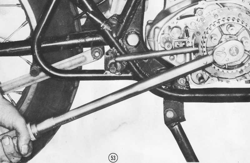
92) Install the footpegs, each with a large bolt and lockwasher. Tighten the
bolts to 40 ft-lbs. of torque. Grease the brake pedal pivot, and then mount the
brake pedal with the cable housing in the tab on the frame. The return spring
can be forced into position with the ends hooked as shown, by pounding the pedal
onto the pivot shaft with a soft-faced mallet. Secure the pedal with a washer
and a cotter pin.
93) Hook the brakelight switch spring to the cable pivot pin and to the switch
as shown. CAUTION: The
spring must hook onto the cable pivot pin between the washer and the clevis to
prevent its falling off.
94) Check the oil tank banjo bolt screen for clogging or damage. Put the banjo
bolt into the fitting, with a washer on each side, and then screw it into the
bottom of the oil tank. On models with plastic oil tanks, push the
tube over the nipple on the bottom of the tank, and then slide the spring wire
clamp into place. Fasten the side cover over the tank.
95) Slip the kickstarter pedal boss onto its shaft, with the reference marks
made during disassembly aligned. CAUTION: Be sure the spring and detent ball are
in place in the pedal and work freely. Position the pedal on the boss, and then
insert the pivot bolt. Insert
the clamp bolt and tighten it securely. NOTE: A small drop of oil on the detent
ball and at the pivot points will make the kickstarter pedal fold as easily as
it is going to; any more oil here will only make a mess. CAUTION: If the pedal
is mounted at the wrong angle on the shaft it could knock a hole in the right
engine cover, or shorten the effective kick stroke, making starting difficult.
96) Screw in the tachometer cable ring nut, and then fasten the oil pump cover
in place with the rubber grommet carefully fitted around the upper edge of the
cover. NOTE: On some models, this cover also has a rubber drainpipe or a rubber
plug in the bottom or toward the front.
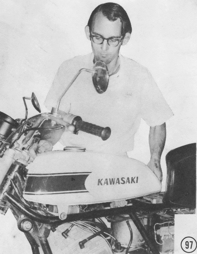
97) Lower the fuel tank into place. Early H1 fuel tanks mount with two bolts in
front, which also hold the amber side reflectors, and one under the front of the
seat. Other models have two rubber mounts on each side of the frame behind the
steering head. Channels on the inner edge of the tank fit over the mounts by
sliding the tank forward. The rear is held in place either by a rubber strap or
by a pin on the bottom of the tank, which fits into a rubber mount on the frame.
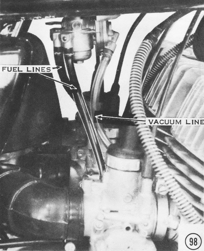
98) Push the fuel line from each carburetor float bowl onto an outlet from the
fuel cock. On H-series models, fit the tube from the right-hand carburetor body
onto the vacuum fitting on the fuel cock. Be sure the wire clamp is in place on
each connection.
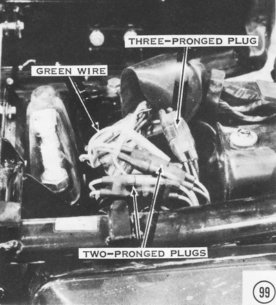
99) Route the wiring loom from the engine between the vertical frame tubes above
the swingarm pivot. H1 models from 1969 through 1971 have four single connectors
and one triple plug to be fastened. 1972 H1's have six single connectors and one
triple plug. 1973 H1's and all H2's have five single connectors and two
double plugs. All other H1's have two single connectors, two double plugs, and
one triple plug. All S-series models have one triple plug and two quadruple
plugs (even though one has only three wires). CAUTION: Check the wiring diagram
in the specifications section of Chapter 7, Electrical System Service, to be
sure your wiring is correct according to the color codes.
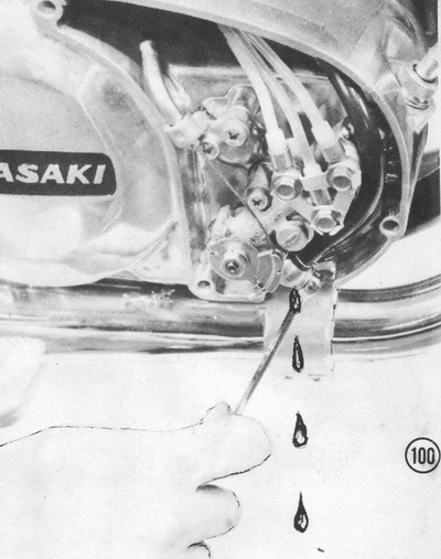
100) Fill the oil tank with a good two-stroke oil such as Kawasaki K-2. CAUTION:
Be sure the oil tank vent hose or the vent in the tank cap is not blocked in any
way. If the tank is not properly vented, the engine will not get enough oil and
will be severely damaged. Remove the oil pump cover. Loosen the oil inlet banjo
bolt on the oil
pump and allow the oil to flow out for about two minutes. This will remove any
air bubbles from the line between the tank and the pump. If the flow stops or is
sluggish, check for blockage. Tighten the banjo bolt securely, then check the
outlet banjo bolts for tightness. NOTE: The H2B has four outlets; all others
have three.
101) Loosen the locknuts and shorten the cable adjusters all the way, at the
handlebar, on the throttle and cold-start cables.

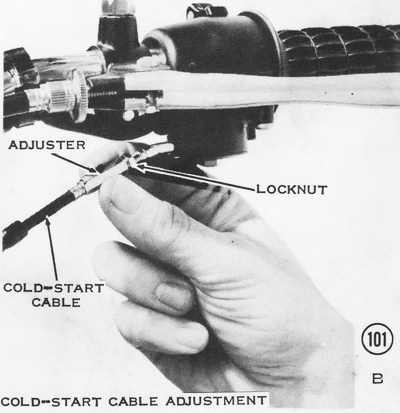
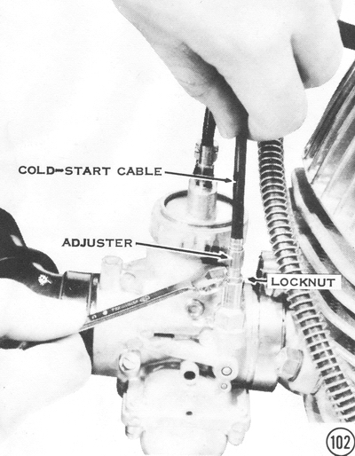
102) At the carburetors, raise the rubber dust covers on all six cables. Loosen
the locknuts on the cold-start adjusters until each cable has 1/8" to 1/4" of
free play. Tighten the locknuts, and then slip the dust covers back down.
103) Remove the cable holder clips from the throttle cable adjusters and loosen
the locknuts. Screw the adjusters all the way in to obtain plenty of cable
slack. Turn the idle adjusters, on the H1 and S1, all the way in; turn the idle
adjusters on the H2, S2, and S3 all the way out. Now the throttle slides are all
in the same position: completely closed. Lengthen each adjuster until each cable
has the same amount of free play: about 1/16". Tighten the locknuts and replace
the cable clips in the adjusters. Be sure the cables are held securely by the
clips. Slide down the dust covers. Now readjust the cables at the handlebars.
Turn the throttle cable adjuster until the cable has 1/16" to 1/8" free play.
Turn the cold-start cable adjuster until the cable has 1/8" to 1/4" free play.
Tighten both locknuts securely. Check the specifications section of Chapter 3,
Fuel System Service, for the correct setting for your machine, and then adjust
the air screws.
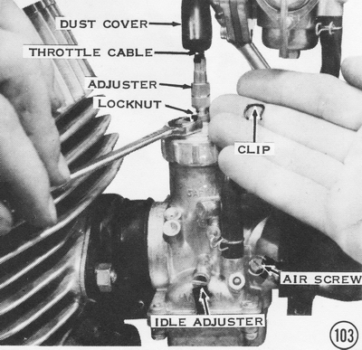
104) Start the engine and hold it at a steady 1,500 to 2,000 rpm. Hold the oil
pump control lever all the way open as shown, until the exhausts smoke heavily
and all the air bubbles disappear from the pressure lines. If the exhausts do
not smoke or the bubbles persist, stop the engine and check for leaks or
obstructions in the line from the oil tank.
NOTE: If lines do not fill properly it may be caused by defective pump,
poor sealing of line fittings, or sticking/contaminated check valves at the cylinder base. Early model check valves
are easily disassembled for inspection/cleaning. Cracking pressure for check
valves should be 4.5 to 4.6 PSI.
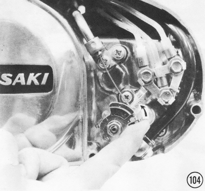
105) While the engine is running, turn the idle adjusters out on H1's and S1's,
and in on H2's, S2's. and S3's until the engine idles at a steady 1,300 to 1,500
rpm. To balance the idle, hold your hand behind each exhaust pipe to feel the
pressure of the exhaust. On H1's and S1's, turn the adjuster in on a "strong"
cylinder, and out on a "weak" cylinder. On H2's, S2's, and S3's, turn the
adjuster out on a "strong" cylinder, and in on a "weak" cylinder. When all three
exhausts are equal switch off the engine.
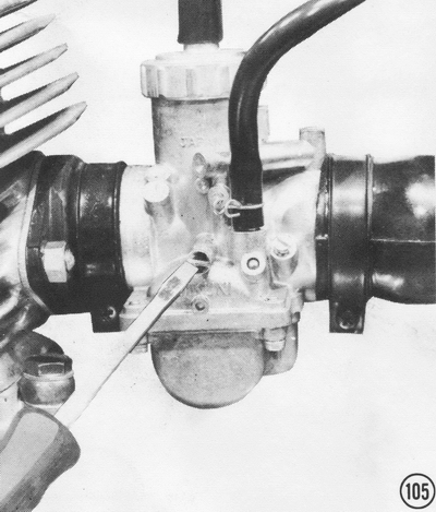
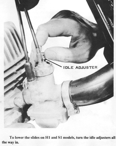
106) Only after having made all carburetor adjustments, adjust the oil pump. The
mark on the oil pump lever should align with the mark on the pump as shown when
the throttles are just beginning to open. If the marks do not align, loosen the
locknut and turn the adjuster on the cable under the fuel tank. Tighten the
locknut. CAUTION: Be sure to make this adjustment accurately. Too lean a pump
setting will cause engine seizure. NOTE: If this setting produces an excessive
amount of smoke on 1969 thru 1971 HI 's, the pump should be readjusted at
wide-open throttle so that the dot noted in the illustration aligns with the
mark on the pump body. Replace the oil pump cover.
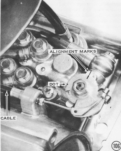
107) To adjust the drive chain, loosen the brake adjuster, the chain adjuster
locknuts, axle nut, and sleeve nut. NOTE: Some models do not have a sleeve nut.
Turn the chain adjusters until the chain has 5/8" to 3/4" up and-down movement
halfway between the sprockets. Be sure the adjuster marks are on equal divisions
on the swingarm tabs on both sides. This will insure proper wheel and sprocket
alignment for good handling and long chain and sprocket life. Tighten the
locknuts, the sleeve nut, and the axle nut. Torque the axle nut to 55 ft-lbs. on
H1 and S-series models, and to 87 ft-lbs. on H2's.
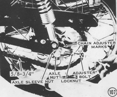
108) Loosen the locknut on the brake pedal adjuster bolt, then turn the adjuster
bolt until the brake pedal is even with the top of the footpeg. Tighten the
locknut. The pedal should have about 1" of free travel before the brake is
applied. If it does not, turn the adjuster at the rear wheel. Turn on the
ignition, and then push the brake pedal. The brake lamp should light when the
pedal is depressed about 5/8" to 3/4". If it does not, loosen the lower nut on
the rear brakelight switch and turn the upper nut as required. Tighten the lower
nut, and then check the brake light again to see if the adjustment has shifted.