Triple Maintenance Manual
Section 5 -
Clutch & Transmission Service
All Kawasaki three-cylinder models offered for sale to the
general public have had oil-bath-type clutches. The racing H1R's and H2R's
are equipped with dry-type air-cooled clutches. Only the wet-type clutch of
the standard-production motorcycles will be covered.
CLUTCH
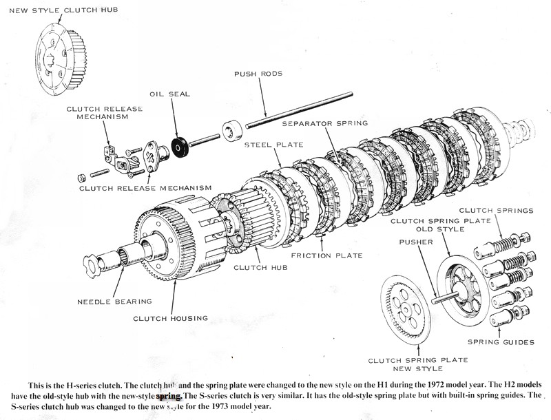
The clutch is a multiplate one with alternating steel and friction plates.
These friction plates are turned by the clutch housing. The tabs on the
outside edge of each friction plate fit between the fingers on the clutch
housing. The steel plates are splined on their inner edges. These splines
engage the splines of the clutch hub in the center of the clutch. The hub is
in turn splined to the transmission driveshaft. The springs of the clutch
spring plate press the steel and friction plates together to engage the
clutch. The power of the engine is transferred from the primary pinion (on
the end of the crankshaft) to the clutch housing, which turns the hub
through the clutch plates. The hub turns the transmission. To disengage the
clutch, a rod pushes through the center of the hollow driveshaft and forces
the clutch spring plate away from the clutch plates. The plates are
separated by rippled circular springs that act on the spline teeth of the
steel plates. Without them the clutch would drag when the lever was pulled,
even though properly adjusted.
TRANSMISSION
All three-cylinder Kawasaki's have constant-mesh, five-speed transmissions
in two basic variations. Each shaft has five gears on it, each of which is
constantly meshed with the corresponding gear on the opposite shaft. Some of
the gears are splined or fastened permanently to the shaft and some are free
to spin on the shaft. On each shaft, the splined or fixed gears alternate
with the free-spinning type. A splined or fixed gear on one shaft always
meshes with a free-spinning gear on the other shaft and vice-versa. Three
gears in the transmission, two on the driveshaft. and one on the output
shaft are splined and have circumferential grooves into which forks fit. The
forks ride on shafts or on a drum that has cam grooves in its surface which
move the forks laterally when the drum is rotated. Turning this shift drum
moves the forks and, with them, the splined or "slider" gears. The slider
gears have dogs (square or round projections) on their sides which can
engage other dogs or holes in the adjacent free-spinning gears, thereby
locking them to the shaft on which they ride. This transmits the rotation of
the driveshaft to the output shaft. Each gear ratio is selected by moving
the splined slider gears sideways to engage different free-spinning gears.
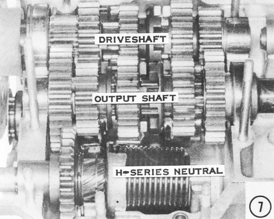
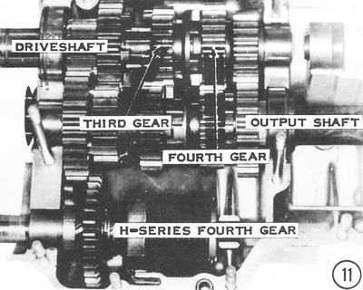
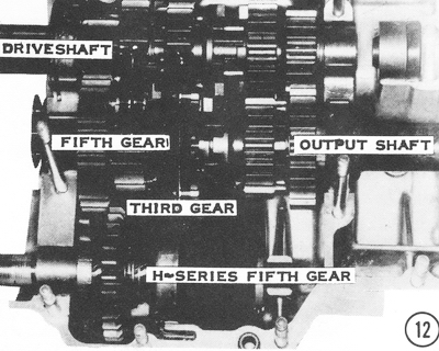
The accompanying illustrations show how the power is transmitted through the
gears. Only one set of three gears is actually transmitting power at any one
time.
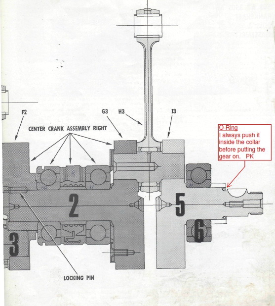
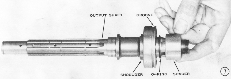
Note: The O-Ring shown behind the engine sprocket
should be located under the spacer.
The shift drum can rotate to any of six possible positions to select the
five "speeds" and neutral. The shift drum is rotated by a ratchet mechanism
that hooks onto six pins in the end of the drum. The shift drum "set levers"
are spring loaded to lock the drum into any one of the six possible
positions. When the shift pedal is moved, the hooks on the ratchet pull or
push on the drum pins to rotate the drum. When the shift pedal is released,
it returns to its rest position (it is spring loaded) and the drum is locked
into position.
As mentioned previously, there are two basic transmissions used in the
Kawasaki three-cylinder models. All the S-series models (S1 through S3) have
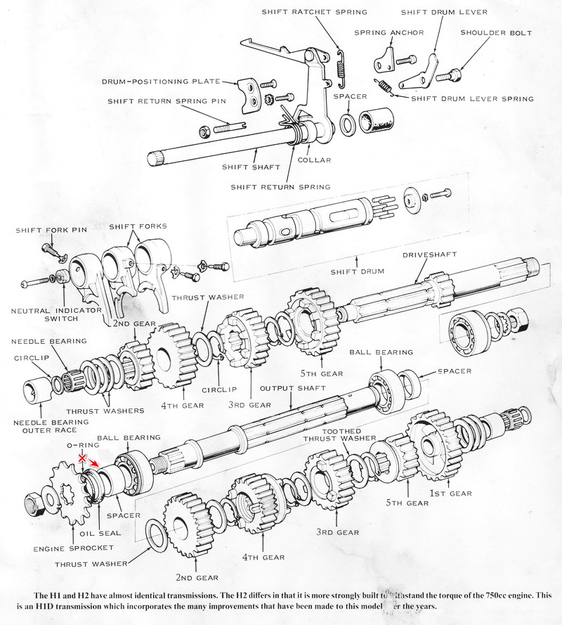
the same transmission. The H1 and H2 models have a similar transmission, but
there are almost no interchangeable parts between the two H-series
transmissions and the S-series transmission. Very few of the same parts are
used in the H1 and H2 transmissions, though the transmissions are almost
identical. Most differences in the H1 and H2 transmissions lie in the
different gear ratios required for the two engines, whose power
characteristics are very different. The H1 is essentially a high-speed
engine whereas the H2 is capable of good horsepower output at relatively low
rpm.
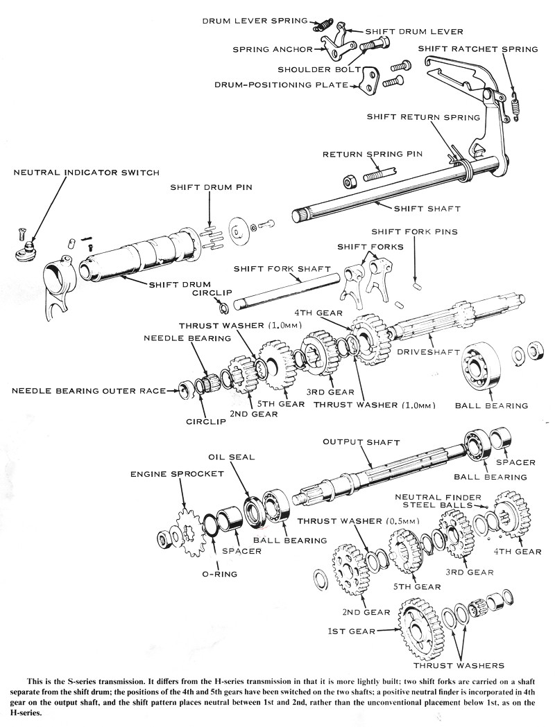
There are three principal differences between the H- and S-series
transmissions. The most noticeable difference is how the shift forks are
supported. In the S-series transmission, the 4th/5th shift fork is carried
on the shift drum and the 1st/3rd and 2nd forks are carried on a separate
shaft (but are still controlled by the drum). In the two H-series
transmissions all three of the shift forks ride on the drum. The other
difference is in the order in which the gears are stacked on the shafts. In
the S-series transmission, the order (from the right-hand side of the
engine) is 1st, 4th. 3rd, 5th, and 2nd. In H-series transmissions the order
is 1st, 5th, 3rd. 4th. and 2nd. The third major difference in the S- and
H-series transmissions is the positive neutral finder of the S-series. The
H-series does not have this feature, because its shift pattern is slightly
different from the S-series pattern in that neutral is on the "bottom" of
the pattern below 1st, instead of between 1st and 2nd as in the S-series.
This pattern makes it easier to find neutral on the H-series machines when
idling. The positive neutral finder does the same for the S-series
transmission.
The positive neutral finder consists of three balls that rest in grooves in
the transmission output shaft, inside of holes in the inner circumference of
4th gear. Fourth gear, in this transmission, is moved to the right to engage
1st gear. The balls are carried along with 4th gear when it is moved to
change gears. The grooves are cut so that 4th gear can move to the right to
engage 1st gear while the motorcycle is stopped, but they will not allow 4th
gear to move far enough to the left so that the shift drum can rotate far
enough to push 5th gear to the left and engage 2nd. In other words, when the
motorcycle is standing still, neutral can be selected from 1st gear or
vice-versa; but the transmission will not go beyond neutral into 2nd. It
stops positively in neutral when shifted up from 1st gear. However, when the
bike is in motion the output shaft is turning, and the balls are forced
outward by centrifugal force into the holes in 4th gear until they no longer
engage the grooves in the output shaft. At this time the gear can be moved
far enough to allow the transmission to shift beyond neutral into 2nd.
Note: The
output shaft should be shown and assembled in the following sequence: ball
bearing, o-ring, spacer, oil seal, sprocket where no chamfer is present on
spacer.
SERVICING THE CLUTCH AND TRANSMISSION
DISASSEMBLING
The disassembly of both the S- and H-series transmissions and clutches is very
similar, and it is covered together in the engine disassembly section of Chapter
4.
CLEANING AND INSPECTING
When the transmission and clutch have been disassembled, wash the parts in clean
solvent. CAUTION: Do not use gasoline or an alkaline solvent. Use a
commercially available solvent sold especially for cleaning engine parts.
Gasoline is a fire hazard, and alkaline solvents will attack the aluminum parts.
If a source of compressed air is available, it should be used to blow the
parts dry. CAUTION: Do not spin the ball bearings with compressed air, as
they have no lubricant after being cleaned and will be ruined. When the
bearings have been cleaned and dried, lubricate them with 20- or 30-weight oil,
and then spin them with your fingers. If they spin freely with no grinding or
scraping noises, they are in good condition.
CLUTCH
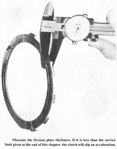
If the clutch has been slipping, the most common causes are worn friction plates
and weakened springs or improper oil. Measure the thicknesses of the friction plates and compare
them to the specifications at the end of this chapter. If any of the plates are
thinner than the service limit, they must be replaced. Check the friction plates
carefully for cracks, breaks, or glazing. Each of these problems can cause the
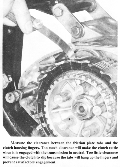
clutch to slip, and in each case the plates must be replaced. Measure the
clearance between the friction plate tabs and the clutch housing fingers with
the plates set into the clutch housing. If the clearance is greater than the
specification given at the end of this chapter, the plates and possibly the
housing will have to be replaced.
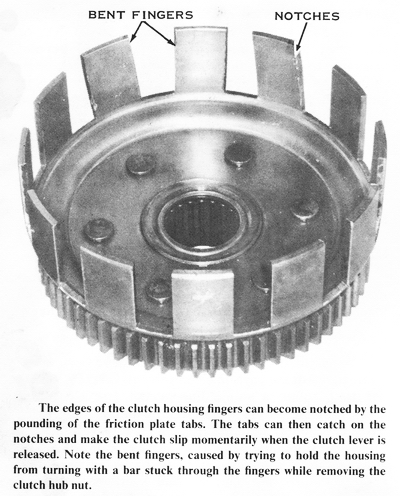
The clutch housing on S-series models is hard, anodized aluminum and can be worn
at the fingers by the friction plate tabs. This wear is in the form of notches
which can catch the plate tabs during engagement and make the clutch slip
momentarily.
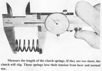
Measure the lengths of the clutch springs and compare them to the specifications
at the end of this chapter. If the springs are shorter than the service limit or
if the shortest spring is over 2.0mm shorter than the longest, the springs must
be replaced. CAUTION: Do not shim the springs to make the clutch "stronger."
The extra tension will press the clutch release rods together so tightly that
the ends can weld together from the extreme heat of friction. Also, the clutch
pull will be very stiff, and the clutch release mechanism will wear out in a
very short time. Special stiffer clutch springs, that are sold for racing use,
can also produce these results unless these precautions are taken: do not hold
the clutch disengaged for more than a few seconds at a time, and frequently
disassemble and lubricate the release mechanism with heavy grease.
The clutch release mechanism is a nylon screw inside a nylon
nut. When the screw is turned it travels inside the nut, pushing on the clutch
pushrods. These rods push the clutch spring plate, and this relieves the
pressure of the clutch springs on the steel and friction plates to allow the
clutch to disengage. If the release mechanism is adjusted too tight or if the
clutch cable has no slack, the clutch will slip and wear out prematurely.
Check the pushrods for straightness by rolling them on a flat surface. The ends
of the pushrods should not be galled. Slight damage can be cleaned up with a
fine oilstone or a piece of fine-grit emery paper on a hard, flat surface. Do
not attempt to repair a badly damaged pushrod end, as you will remove the
case-hardened outer shell. The softer material thus exposed would wear very
quickly under the extreme pressure present when the clutch is disengaged.
All H2 models have a 5/16" steel ball between the end of the long pushrod and
the clutch spring plate pusher. This steel ball must not be worn or discolored;
if it is, replace it. The ends of the pushrods can also be discolored. If the
discoloration is severe, they must be replaced. The discoloration is evidence of
heat buildup caused by lack of lubrication or by holding the clutch disengaged
for long periods of time, as when waiting at a stoplight.
The bushing and needle bearing inside the clutch housing do not ordinarily wear
very much. To test for wear hold the bushing about halfway out of the rear of
the housing and rock it sideways. If it moves perceptibly, replace the bushing
and the housing.
The clutch gear is fastened to the back of the housing with rivets and
incorporates rubber dampers to cushion the shock of clutch engagement. Twist the
gear while holding the housing. If the gear moves easily, the entire housing
must be replaced, because the rubber dampers are worn out. If the gear can be
pulled away from the back of the housing perceptibly, the rivets have stretched,
and the housing assembly must be replaced. The clutch housing comes complete
with the gear as a replacement part.
Inspect the teeth of the clutch gear and primary pinion for wear marks or
erosion. Either type of damage will cause a whining noise from the primary
drive. If either gear has definite wear marks, eroded or broken teeth, both
gears should be replaced. Minor damage to the gear teeth can be dressed with an
oilstone.
TRANSMISSION PARTS
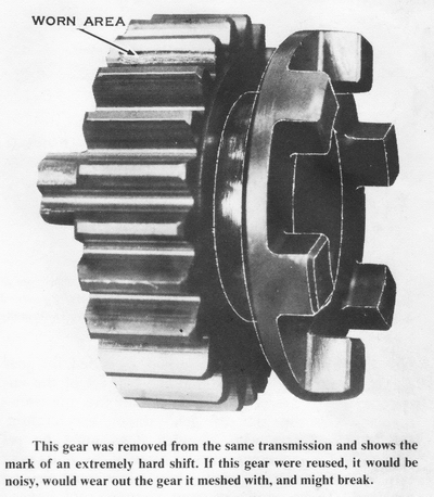
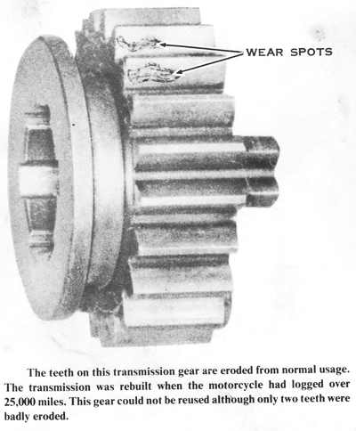
Inspect all transmission gears, including the kickstarter gears.
If any teeth are chipped or broken, or if the faces of the teeth are heavily
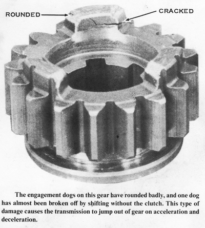
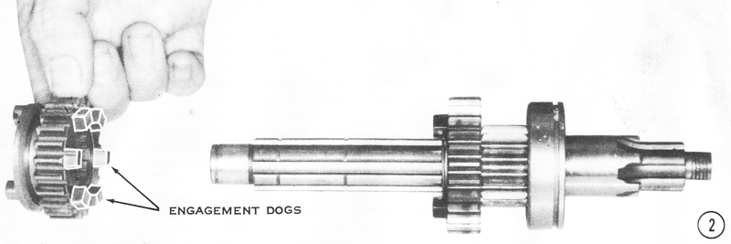
marked or eroded, the gear should be replaced. Check that the corners of the
engagement dogs are not rounded. If they are, the transmission will slip out of
gear under acceleration. CAUTION: Gears with rounded dogs must be replaced.
The engagement holes in some of the gears may have rounded edges as well. These
gears must also be replaced. These kinds of gear damage are caused primarily by
improper riding habits; sudden starts, hard or incomplete shifts, and shifting
without the clutch are hard on transmission gears.
Inspect the inside diameter of the output shaft 1st gear and of the driveshaft
5th gear. If the gear is discolored around the hole or if the bushing is worn so
that the small oil dimples have disappeared, the gear must be replaced. These
two gears, more of the time than any of the other gears, turn at a speed
different from the shaft on which they ride. Therefore, they are the most likely
to show this type of wear. If the gear has discolored (turned a blue black color
around the hole), it has overheated from lack of lubrication, caused by an oil
leak. Check the shafts for the same discoloration and replace them if they have
turned blue black anywhere from heat. The discoloration is caused by the heat
changing the hardness characteristics of the metal's surface. If these parts are
reused, they will wear out quickly. and can cause other damage at the same time.
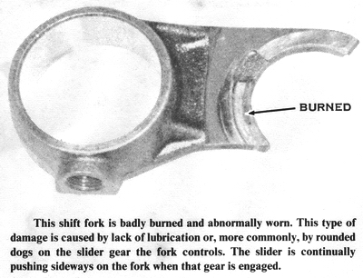
The ends of the shift forks that fit into the grooves in the
gears are the most likely spots to wear. To check for this wear, slip the fork
into the groove of the gear it shifts, and measure the clearance between the
fork and the groove with a blade-type thickness gauge. The clearance should be
0.05 to 0.25mm (0.0020 to 0.0098 in.). If the forks are worn and have slightly
more clearance. they are still usable if the clearance is 0.6mm (0.024 in.) or
less, as this is the service limit. If the clearance is greater than this,
replace the fork and the gear. The ends of the fork can also be discolored by
overheating caused by lack of oil. If they are discolored, they must be
replaced. Check the groove in the corresponding gear as well. If it is also
discolored, replace it. Check the pins on the forks that ride in the grooves in
the shift drum. If they are noticeably worn, they must be replaced to insure
smooth, positive shifting. CAUTION: Bent shift forks cannot be straightened;
they must be replaced.
Many oil leaks can be traced to faulty oil seals. Check the inner lip of the
seal to be sure it is smooth. If the seal is cracked or torn, it will leak.
Check the surface of the shaft where the seal rubs against it. If it is
scratched or nicked, it will quickly wear out a new seal.
The transmission shafts must be straight and smoothly finished all over. As
mentioned above, discoloration means overheating. Small nicks and scratches on
the splines or on the seal surface can be repaired, if they are not too deep, by
lightly polishing the affected spot with a piece of fine-grained emery cloth
that has been oiled. Wrap the emery cloth around a steel bar or a wrench handle
to make it easier to handle.
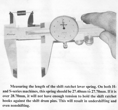
Inspect the shift ratchet mechanism for cracks, or bent or
broken parts. Extreme wear on the ratchet hooks or weakened springs will cause
poor shifting. Measure the springs with a vernier caliper. If they are longer
than the specifications listed at the end of this chapter, they have lost their
tension and must be replaced. If the straight ends of the shift return spring
are bent or worn, the shift lever may not return to center after shifting.
Replace the return spring if it is damaged.
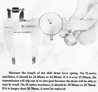
The shift drum levers hold the shift drum in position when a gear has been
selected. If the rounded ends of the levers are worn, if the pivot holes or
pivot step-bolt are worn, or if the spring has lost its tension, the
transmission will overshift on both up and down shifts and can slip out of or
into gear at any time.
The return spring pin must be tight in the engine case or under- and
overshifting can result. If the pin is loose and cannot be tightened, the case
threads are stripped. The most reliable repair (and the most expensive) is to
replace the crankcase set. The top and bottom halves are not available
separately. If this is not feasible, remove the pin and clean the threads and
the hole in the case with an oilless solvent such as trichloroethylene. Coat the
threads with a layer of a permanent threadlocking compound such as Kawasaki
Super Liquid Lock-K or Loc-tite Formula B. Screw the pin into the case as
tightly as it will go without slipping, and allow it to cure for at least six
hours in a warm, dry place.
The shift ratchet lever on the end of the shift shaft must be tightly fastened
in place. If it is not, it may be welded or replaced. If it is welded, be sure
the welding does not obstruct the bushing that goes inside the coil of the
return spring, and that it does not get on the flat end of the shift shaft on
S-series models, as the flat end bears against a boss in the right-hand engine
cover to locate the shaft. On H-series models, the shaft protrudes through the
right-hand engine cover to allow an optional shift lever to be mounted on the
right side. The end of the shaft in this case must not have any weld splatters,
or the oil seal in the right-hand engine cover will be destroyed and leak oil.
ASSEMBLING THE S-SERIES TRANSMISSION
This section will cover only the assembly of the S-series transmission. The
disassembly of the S- and H-series transmissions and the assembly of the
H-series transmission are covered in Chapter 4.
During transmission assembly, be sure to keep all parts as clean as possible.
After the transmission has been assembled and installed in the upper half of the
engine crankcase, pour a liberal quantity of good quality gear over the transmission gears before joining the case halves. Use the
same oil to fill the transmission after the engine has been installed in the
frame.
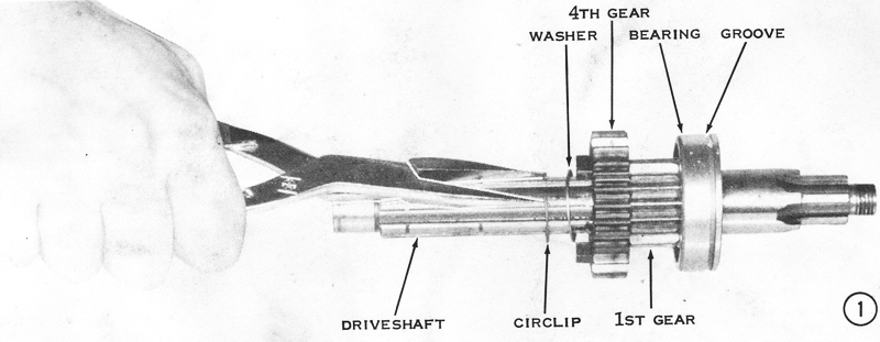
DRIVESHAFT
1) Install ball bearing number 6205N on the threaded end of the driveshaft, with
the groove facing away from the 1st gear teeth. Push the bearing solidly against
the gear teeth. Slip the driveshaft 4th gear (25 teeth) onto the other end of
the shaft, with its engagement dogs facing away from the gear teeth machined on
the shaft. Install a 1.0mm-thick toothed washer and secure the gear and washer
with a new circlip in the groove closest to the gear. CAUTION: Be sure the
sharp edge of the circlip faces away from the washer. The sharp edge holds the
groove of the shaft better than the rounded edge. CAUTION: New circlips must be
used, as the old ones lose their tension. If a circlip comes loose, the
transmission could shift erratically or slip out of gear.
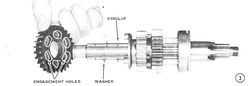
2) Install the driveshaft 3rd gear (23 teeth) with its 6-dog
side facing toward the gear just installed.
3) Install a circlip, with its sharp edge toward the 3rd gear.
Slip a l.0mm-thick toothed washer onto the driveshaft, and then install the
driveshaft 5th gear (27 teeth) with its dog engagement holes facing toward the
3rd gear.
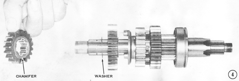
4) Install another l.0mm-thick toothed washer, and then slide the 2nd gear
(19 teeth) into place. CAUTION: The chamfered inner edge of the gear must
face the washer just installed. If it is turned around, the gear will crush the
circlip and bend it out of its groove during shifts into 5th gear. This would
allow the transmission to slip out of 5th gear.
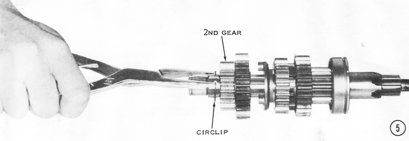
5) Using circlip pliers, install the last circlip in the final
groove with its sharp edge facing away from the driveshaft second gear.
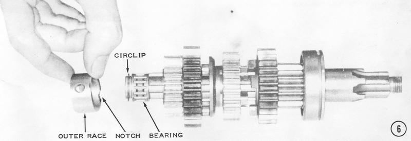
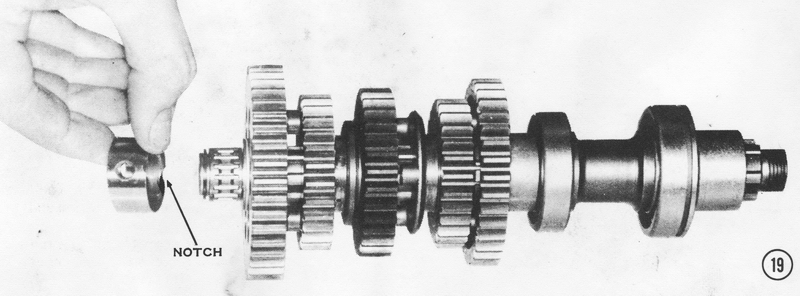
6) Slide on the caged needle bearing. Secure it with a small
circlip, and then slip the outer race over the needle bearing with the notched
edge toward the gears on the shaft.
OUTPUT SHAFT
7) Install ball bearing number 6205N onto the threaded end of the output shaft,
with the groove facing away from the shoulder. Slip the O-ring into place as
shown, and then push on the sprocket spacer until the 0-ring is squeezed between
it and the bearing.
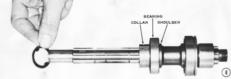
8) Slip the smaller ball bearing, number 6005, onto the long end
of the shaft and seat it against the shoulder. Put on the collar and a
0.5mm-thick toothed washer.
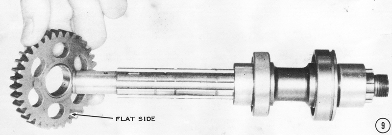
9) Install the output shaft 2nd gear (34 teeth), with its flat
side against the collar (recessed side away from the collar).
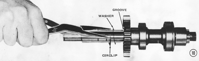
10) Put another 0.5mm-thick toothed washer on the output shaft
next to the gear just installed. Secure it with a circlip in the groove closest
to the gear. The sharp edge of the circlip must face away from the washer.
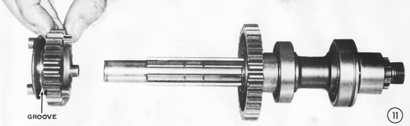
11) Slip the output shaft 5th gear (26 teeth) onto the shaft so
that its shift fork groove is facing away from the output shaft 2nd gear
installed in step 9.
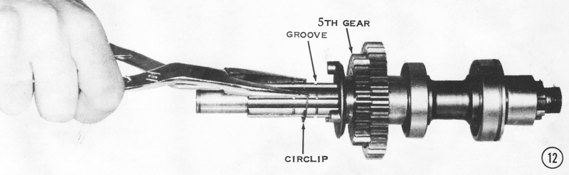
12) Install a circlip into the next groove with its sharp edge
facing toward the 5th gear.
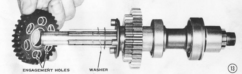
13) Slip on a 1.0mm-thick toothed washer, and then install the
3rd gear (31 teeth), so that its dog engagement holes are facing toward the
gears already installed.
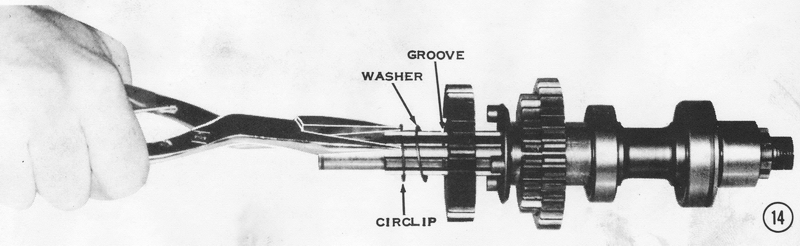
14) Add another 1.0mm-thick toothed washer, then install a
circlip in the next groove with its sharp edge away from the toothed washer.
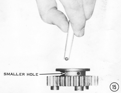
15) To install the output shaft 4th gear, position it on a flat
surface with the holes toward the top as shown. From the inside, insert one
steel ball into each of the three small holes. CAUTION: Do not use grease to
hold the balls, as this will prevent the mechanism from working properly. The
grease will hold the balls out of the slots in the output shaft, making the
neutral finder inoperative until the grease is melted by the transmission oil,
which could take hundreds of miles of operation.
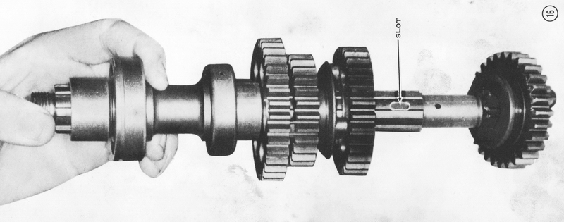
16) Lower the output shaft into the center of the 4th gear. Be
careful to align the shaft so that the balls align with the slots in the shaft.
Now lift the gear care fully onto the splines of the shaft until it is butted
against the 3rd gear. Lay the shaft on its side so one of the balls falls into
its slot. The gear will now be locked onto the shaft. Check that the gear moves
freely back and forth the length of the slot without binding.
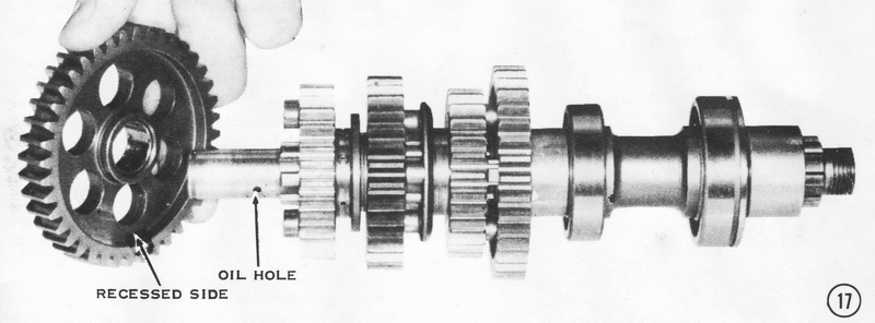
17) Install the 1st gear (40 teeth) with its recessed side
toward the 4th gear. CAUTION: Check that the oil hole is open. If it is
blocked, the gear could seize on the shaft.
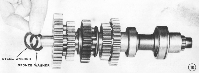
18) Put on the last thrust washers. The phosphor bronze
(yellow-colored) washer goes on first and then the steel washer.
19) Slip on the caged needle bearing and secure it with a
circlip. Slide on the bearing outer race with the notched edge toward the 1st
gear.
INSTALLING THE SHIFT DRUM, FORKS, AND SHAFTS
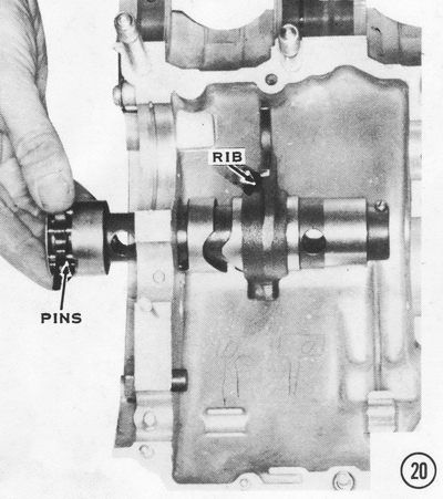
20) Slip the shift drum partway into the side of the upper engine case half.
Slide the 4th-5th shift fork over the drum in the position shown. CAUTION: Be
sure the rib is facing toward the end of the drum with the pins in it.
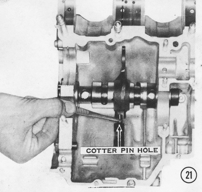
21) Push the drum the rest of the way into the upper case half.
Position the shift fork about halfway along the drum, and then insert the pin,
long end first, into the hole in the shift fork boss. NOTE: The pin fits into
the center of the three grooves in the drum. Note the small hole in the pin,
which must align with the hole through the shift fork boss. Insert a new cotter
pin from the left, and then bend the ends over.
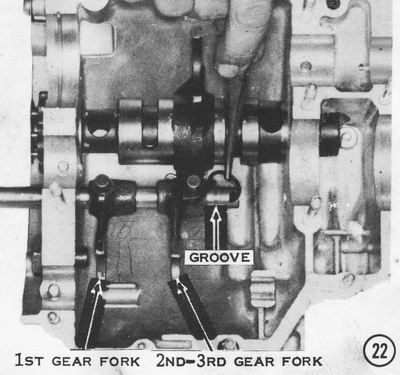
22) Push the grooved end of the shift fork rod into the case,
and then slide the 1st gear shift fork onto it. NOTE: The 1st gear f fork has
the pin in line with the fork ears. Slide on the 2nd-3rd shift fork with the
offset pin. Slide an E-clip into the groove in the shaft, and then push the
shaft all the way into the case. The pins on the forks fit into the other two
grooves in the shift drum.
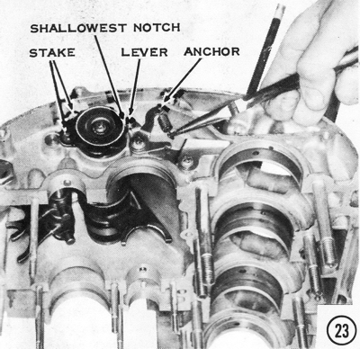
23) Install the drum retainer plate as shown. and then stake the
edges of the countersunk head screws to prevent their loosening. CAUTION: The
screws must be no more than 16mm long or they will go through the case wall and
lock the 1st gear. Position the drum lever and spring anchor as shown, and
then insert the shoulder screw. Be sure the lever moves freely. NOTE: Use
only a round-headed shoulder screw as shown here. A hex-headed shoulder bolt can
catch on the gear-change ratchet, causing erratic or under shifting. A
nonshoulder screw or bolt will prevent the lever from working freely.
CAUTION: Do not overtighten this screw, as it can prevent the lever from holding
the drum in position, which will allow the transmission to slip out of gear and
make precise gear changes impossible. Hook the spring between the levers as
shown. CAUTION: The upper end of the spring must hook toward the inside, or
the end of the spring could catch on the clutch gear and be damaged. Turn
the drum so that the roller on the drum lever fits into the shallowest notch in
the plate on the end of the drum as shown. so that when assembled the
transmission will be in neutral.
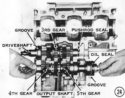
24) Put the oil seal over the sprocket spacer on the output
shaft with the marked side facing out, and then position the two shafts in the
case as shown. The shift fork on the drum must fit into the groove in the
driveshaft 3rd gear. The shift forks on the shaft must fit (from left to right)
into the grooves in the output shaft 4th and 5th gears. The grooves in the ball
bearings on both shafts must fit the alignment rings in the case. The needle
bearing outer races on both shafts have holes that must fit on alignment pins in
the case. Install the clutch pushrod oil seal flat against the end of the output
shaft with the marked side facing out.
ADJUSTING THE TRANSMISSION GEAR ENGAGEMENT
After you have completed assembling the transmission shafts and the shifting
mechanism, but before you join the engine crankcase halves, check the gear
engagement in each of the six positions. The gear positions are illustrated in
the photos.
If you have experienced transmission shifting problems or if your transmission
goes out of or into gear by itself, it should be adjusted by adding shims
(special washers of certain thicknesses) in some locations. The following
procedures describe how to adjust the S- and H-series transmissions.
Some extra parts may be needed for adjusting your transmission. In the S-series
procedure, the 0.5mm-thick washers can be purchased from a Kawasaki dealer as
part number 92024-035: the 1.0mm-thick washers are listed as part number
92024-034. In the H-series procedure, the part numbers are listed as they are
required, as there are different numbers for the washers used in different
places.
S-Series Models
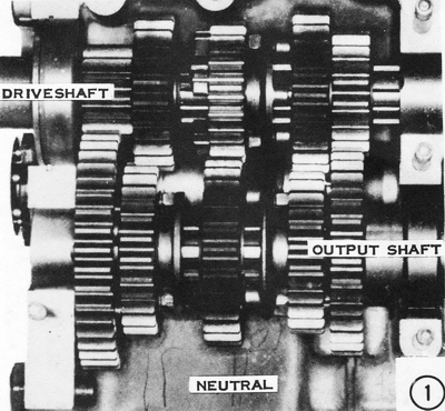
1) NEUTRAL. When the transmission gears are in this position, none of the
dogs on the three slider gears are engaged with the dogs or holes on the
adjacent gears. Check that each shaft turns freely without interfering
with the other. A slight tendency for one shaft to turn the other is acceptable.
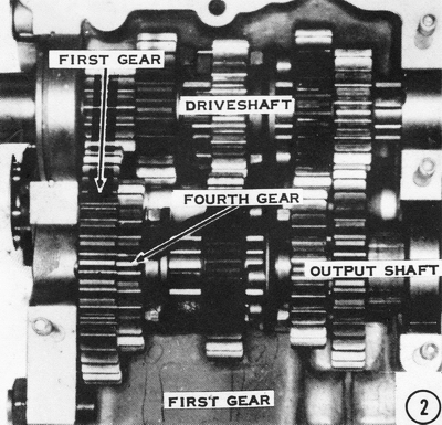
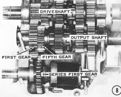
2) FIRST. While slowly turning the driveshaft, turn the
shift drum clockwise to shift the gears into this position for first
gear. The shift dogs of 4th gear on the output shaft should show from the back
through the holes in the 1 st-gear output shaft. If they do not, check that
there are two 1.0mm thrust washers between it and the wall of the case. If the
dog engagement is still not sufficient with two washers, check for a bent shift
fork or a worn shift fork pin.
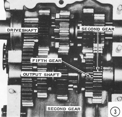
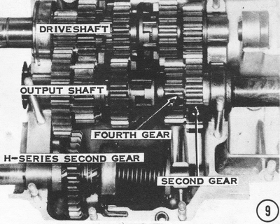
3) SECOND. Hold the top neutral finder mechanism ball up
with a magnetized pin punch or similar magnet, and then turn the shift drum
counterclockwise until the gear positions are like this for second gear. There is one
0.5mm thrust washer on each side of the 2nd gear output. If the 5th gear output
does not mesh with it completely, both washers should be put on the outside of
the gear (on the side toward the engine sprocket). CAUTION: If both thrust
washers are moved to the outside of the 2nd gear output, 5th gear may not
disengage completely in neutral. Check to be sure this does not happen. If it
does, you must leave the thrust washers as they were originally installed and
look for some other problem. Check for a bent shift fork or a worn shift fork
pin. NOTE: Be sure the bearing-locating ring is in place to hold the
shaft in its proper position laterally.
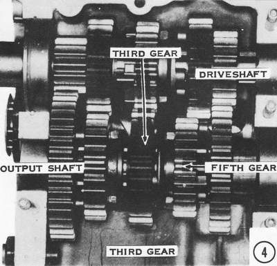
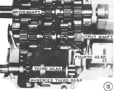
4) THIRD. Turn the driveshaft slowly and shift the
transmission into third gear. Check that the dogs on the 5th gear output firmly
engage the holes in the 3rd gear output. If the 3rd gear output is too far from
the 5th gear output, it can be moved by changing the thrust washers on either
side of it. Originally the gear has a 1.0mm washer on each side. To move
3rd-gear output to either side, replace one of the washers with a 0.5mm washer
and place another 0.5mm washer on the other side with the original 1.0mm washer.
In this manner, the gear can be moved 0.5mm to either side. CAUTION: There
must be at least one 0.5mm or one 1.0mm thrust washer between the gear and the
circlip. If there isn't, the spinning gear will force the circlip out of its
groove and two gears will be engaged at once, causing major transmission damage.
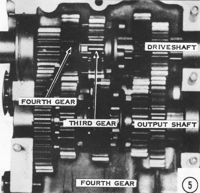
5) FOURTH. Continue to fourth gear by turning the shift
drum farther clockwise. In this position, the driveshaft 3rd gear must firmly
engage the driveshaft 4th gear. The dogs should overlap at least 4.0mm. If they
do not, the driveshaft 4th gear can be moved closer to the driveshaft 3rd gear
by replacing the 1.0mm washer between it and the circlip with a 0.5mm washer and
adding a 0.5mm washer between driveshaft 4th gear and the teeth cut into the
shaft. CAUTION: If the driveshaft 4th gear is moved closer to the driveshaft
3rd gear, check that there is at least 1.0mm clearance between the dogs of the
driveshaft 4th and 3rd gears when the transmission is in neutral. Less clearance
than this will cause the transmission to go into two gears at once under
operating conditions. The driveshaft 4th gear must be moved to its original
position to avoid severe transmission damage. If this is the case, look for a
bent shift fork.
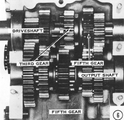
6) FIFTH. Turning the shift drum one more notch clockwise
will shift the transmission, into fifth gear. In this position, the
driveshaft 3rd gear must firmly engage the holes in the driveshaft 5th gear. If
they do not, the driveshaft 5th gear can be moved closer to the driveshaft 3rd
gear by replacing the 1.0mm washer between it and the circlip with a 0.5mm
washer. Add another 0.5mm washer between the driveshaft 5th and 2nd gears.
CAUTION: Again, make sure there is at least 1.0mm clearance between the
driveshaft 5th gear and the dogs on the driveshaft 3rd gear when the
transmission is in neutral. If there is not enough clearance, move the
driveshaft 5th gear back to its original position and look for a bent shift
fork.
H-Series Models
7) NEUTRAL. Some H-series models may need to have the transmission gears
shimmed to make them engage fully and shift properly. This gear position is
neutral. Be sure the shafts can spin independently. A slight tendency for one
shaft to turn the other is normal.
8) FIRST. Turn the shift drum until the gears are in this
position for first gear. If the motorcycle has had a tendency to jump out of
first gear, the output shaft 5th gear may not be engaging the 1st gear output
all the way. Add a 0.5mm washer (P/N 92022-144) between the 1st gear output and
the outer bearing race. If this makes the shaft hard to turn, the washer must be
removed. The problem is most likely a bent shift fork or improperly machined
shift drum. The offending part must be replaced.
9) SECOND. Turn the shift drum another notch, so that the
gears are in this position for second gear. If the unit has had a tendency to
jump out of second, the 2nd gear output may not be close enough to the 4th gear
output. To move it closer, remove the 1.0mm washer between it and the circlip
and replace it with a 0.5mm washer (P/N 92022-225) on each side of the gear.
This moves the 2nd-gear output 0.5mm closer to the 4th gear output. If the dogs
of the two gears now hit each other when the transmission is in neutral, the 2nd
gear output must be returned to its original position; the problem is elsewhere.
10) THIRD. Now turn the shift drum to the 3rdgear
position as shown. A tendency to jump out of 3rd gear is usually caused by the
washer (between the 3rd gear output and the circlip) spinning with the 3rd gear
output and wearing against the circlip. Eventually the circlip is forced out of
the groove in the shaft and the 3rd gear output moves far enough away from the
4th gear output so that their dogs can no longer engage. Replace the worn washer
with a toothed washer (P/N 92024-033) that cannot spin.
11) FOURTH. Turn the shift drum to put the transmission
in 4th gear as illustrated. If the transmission will not stay in 4th, the
4th-gear driveshaft may be moved closer to the 3rd gear drive to allow the dogs
to engage fully. Insert a 0.5mm washer (P/N 92022-144) between the bronze and
steel washers on the end of the shaft near the needle bearing. This moves 2nd
and 4th gears drive closer to the 3rd gear drive. If the shaft turns hard, take
out the shim; the problem is elsewhere. If the shaft turns freely, but the dogs
of 3rd and 4th gears output hit each other with the transmission in neutral,
move the 0.5mm washer to a position between the 4th gear drive and the circlip
that holds it in place. This will prevent the gear from moving on the shaft.
12) FIFTH. Finally, shift the transmission into this
position for fifth gear. To cure a tendency to jump out of fifth gear, first
measure the clearance between the dogs of 5th and 3rd gears, on the driveshaft,
with the transmission in neutral. If the clearance is less than 2.0mm, the
problem is elsewhere. If the clearance is greater than 2.0mm, the 5th gear drive
must be moved closer to the 3rd gear drive for better dog engagement. Remove the
1.0mm washer between the 5th gear drive and its circlip and replace it with two
0.5mm washers (P/N 92022-225), one on each side of the 5th gear drive.
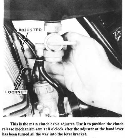
CLUTCH ADJUSTMENT
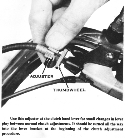
There are actually two adjustments that must be made to assure proper clutch
operation. First, loosen the cable adjuster thumbwheel at the handlebar lever,
then turn the adjuster all the way into the lever bracket to give as much slack
as possible. Next remove the chain case cover. Loosen the locknut on the cable
adjuster. This adjuster is on the clutch cable under the fuel tank, just above
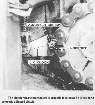
the carburetors. Turn the adjuster until the arm on the clutch release mechanism
points downward at a slight angle from the horizontal, about 8 o'clock. Tighten
the locknut. Now adjust the release mechanism itself. Loosen the locknut. Turn
the adjuster screw in until resistance is felt, back off 1/8 turn, and then hold the screw in that
position while tightening the locknut as shown. Replace the chain case cover.
The hand lever should now have about an inch of free travel at the ball end
before the resistance of the clutch springs is felt. If it does not, loosen the
thumb wheel and turn the adjuster as required. If you wish, the clutch may be
adjusted for more cable slack to place the lever nearer the handgrip. This will
help accommodate a smaller hand more comfortably. CAUTION: Be sure the clutch
disengages entirely when the lever is pulled to the grip. If the motorcycle is
more difficult to push by hand with the engine off, in gear, with the clutch
pulled, than with the transmission in neutral, the clutch is dragging and must
be adjusted with less cable slack.