Click for complete set of installation pictures.
------------STARFIRE ZX Mark 2 -3 CDI INSTALLATION
INSTRUCTIONS FOR KH400------------
This CDI unit replaces completely the existing
Kawasaki CDI unit, and problematic H/L magneto coil in one hit.
REMOVE BATTERY BEFORE INSTALLATION
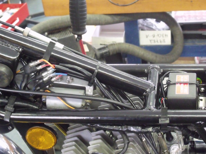
1) Remove the original CDI unit, and mount the Starfire unit in its place using a custom bracket.
2) Identify the three 2 pin Molex style connector in the harness...these six wires are connected to the ignition coils.
3) Connect three of the BLACK wires from the
connectors to the three RED wires from the CDI unit.
CAUTION: 300 volts is present on these terminals when
the key is on.
--------------------IMPORTANT-
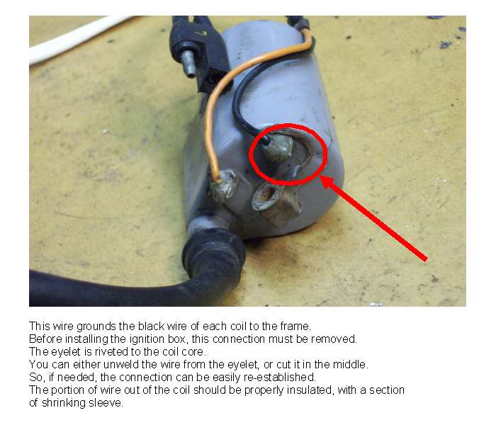
DOUBLE CHECK that all coils are NOT GROUNDED anywhere else. This can be
checked with a multimeter continuity test from the coil primaries to ground.
The grounding wire to the eyelet on each coil must be cut and removed before
going any further.
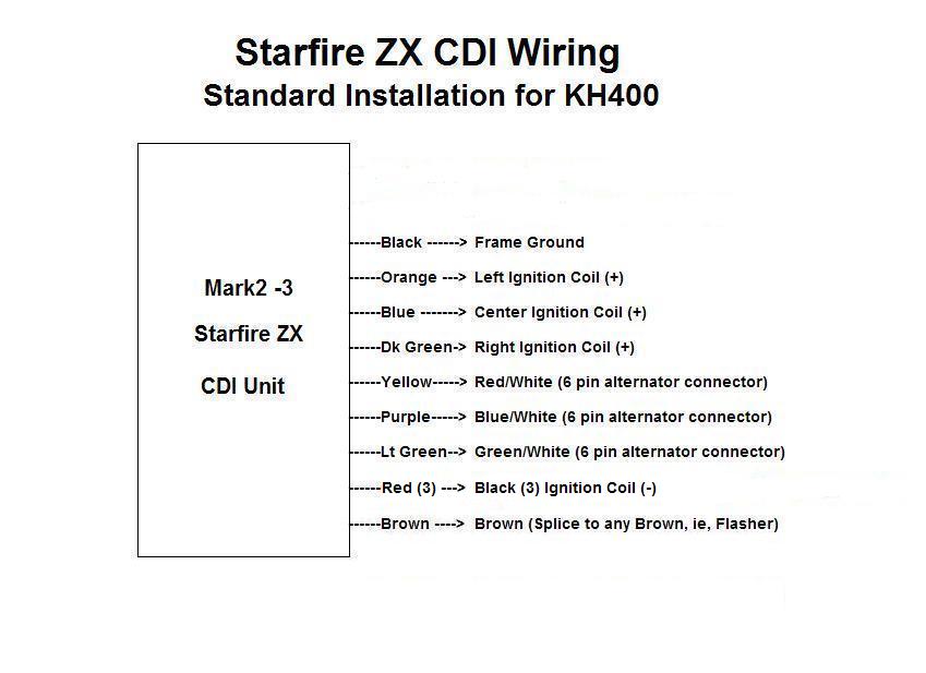
4) Connect the CDI ORANGE, BLUE and DARK GREEN wires to the corresponding colours in the three connectors, one in each.
5) Identify the 6 pin Molex style connector from the alternator housing. These are the magneto coil and trigger coil feeds.
6) Connect the CDI YELLOW to the RED/WHITE (left cylinder)
7) Connect the CDI PURPLE to the BLUE/WHITE (Center cylinder)
8) Connect the CDI LIGHT GREEN to the GREEN/WHITE (right cylinder)
9) Connect the BLACK CDI wire to a firm ground.
10) Connect the CDI BROWN wire to any handy brown wire in the harness... this is the 12 volt supply from the ignition switch. This MUST be zero voltage when key is off.
11) Refit battery after checking your work.
The bike will now run.
The ignition timing will also require setting with a timing
light.
If there is no spark at this point, carefully check there
is 300-350 volts at the coil primaries with the key on....., measure carefully
with a multimeter and double check as in 3 above.
Note: The existing H/L speed magneto coil can be
completely discarded. Its complete function is taken over by the CDI
unit, the high voltage now derived from the 12 volt charging system and
drawing only an additional 12 watts maximum ( 1 amp) from the battery. The
H/L coil can be rewound, similar to the other charging coils to usefully
increase the charging capacity of the bike, possibly by another 2 amps... 24
watts.
Click for Wiring Diagram
------------INSTALLATION INSTRUCTIONS FOR KH400
w/ minimal electrics------------
For minimal equipment dragracing/road racing use,
The Starfire CDI will function as a complete stand alone unit. It is
suggested a small battery pack be used to supply the required voltage. A
pack of 8 2000 mAh AA rechargable NiMh or NiCads will run the unit for
approximately 1.5 hours.
Wire the CDI as follows:
1) Mount the CDI as above.
2) Identify the three NEGATIVE primary terminals on the ignition coils, and connect all three to the three RED wires from the CDI unit... one RED to each coil.
------------------------------
DOUBLE CHECK the ignition coils are NOT GROUNDED anywhere else... as in
(3) above.
3) Connect the three wires from the CDI unit... ORANGE, BLUE, and DARK GREEN to the POSITIVE primary terminals of the three ignition coils. These are RIGHT, CENTER, LEFT
4) Connect the three wires from the CDI YELLOW, PURPLE, and LIGHT GREEN to the three pulse coils (trigger coils). These are RIGHT, CENTER, and LEFT.
5) Connect ONE BLACK wire from the CDI to a firm ground.
6) Connect the BROWN wire from the CDI, to one terminal of a kill switch, or deadmans. The other switch terminal then connects to the POSITIVE of the battery pack, the NEGATIVE of this pack connecting to ground. A suitable POLARIZED plug will be required to assist changing packs between races.