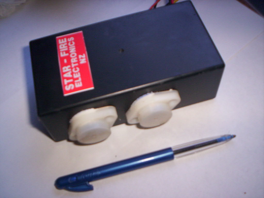
Starfire Early H1
CDI
dayleedwards@rushpost.com
Discontinued - Use ZX Mark2 CDI Replacement
The STARFIRE Capacitor Discharge Ignition (CDI) unit is designed specifically to replace the stock Mitsubishi OEM system on the KAWASAKI Early H1 ('69-'72) motorcycle.
Price is $119US + $25 US shipping (based on exchange rate Oct 4, 2010).
OVERVIEW OF CDI.
Normal points/coil or Kettering ignition relies on the opening and closing of a simple contact breaker, or point system to connect and disconnect a current supply from a battery to the primary winding in the ignition coil. As the current through the coil builds to a maximum, a magnetic field is created in the iron core. When the points open, thereby stopping the current, the rapidly collapsing magnetic field generates a very high voltage in the secondary winding, creating a spark at the plug.
This system is fine for the simple "agricultural" type engines, but causes huge problems when high revs and high compression ratios are required.
As the time the points are closed decreases with increasing RPM's, the time for the core to become magnetically saturated decreases, and the spark energy rapidly decreases. This simple type of ignition is largely unsuitable for high performance engines.
By increasing the voltage applied to the coil primary, the time required to saturate the magnetic core is reduced dramatically.... rather like using a larger hammer to drive a nail. The CDI system uses several methods to increase the performance by these means.
HIGH VOLTAGE INVERTER
The STARFIRE CDI takes the 12 volt supply from the battery, and by an electronic inverter, or oscillator.... the buzz.... increases this to over 400 volts. This voltage is stored in a capacitor, much like having a bucket of volts. At the right time, the capacitor is connected to the coil primary, instantly saturating the core using brute force.
The STARFIRE CDI uses 2 silicon power transistors in a simple and efficient push pull inverter arrangement, and together with a specially designed, and expensive!! power transformer, manages a peak output pulse of over 20 amps into the primary. The oscilliatory nature of the discharge allows some efficiency gain by recovering part of this voltage to be used again in the next cycle.
HIGH VOLTAGE SWITCH
The high voltage cannot be switched using mechanical means, ie points, so an electronic switch is used for this function. This is called a Silicon Controlled Rectifier, or SCR for short. The Early H1 model uses a simple but effective trigger coil and a rotating magnet on the end of the crankshaft to provide a trigger pulse at the correct moment, this being used to fire the SCR. The 400 volt output from the inverter is rectified by a high voltage bridge rectifier circuit, and stored in a specially designed low ESR , high current discharge capacitor, the peak pulse at this point being in the region of several hundred amps for the very short duration of the spark. This current is switched by the SCR, and being of such a very short duration, is operated well within its safe operating area, although theoretically heavily overloaded. The reverse voltage spike, present in all ignition coils, and normally responsible for burning contact breakers, is returned by a high speed diode, or one way switch, to the discharge capacitor in such a way as to add to the next firing pulse. A 30 percent saving in primary current requirement is achieved with this system, and also contributes to the insanely high triggering speeds that the STARFIRE CDI is capable of giving.
TRIGGER AMPLIFIER
The trigger amplifier is required to have conflicting requirements. When starting the bike, the relative movement of the magnetic rotor on the crankshaft to the trigger coil is low, and the pulse level will also be at a very low level, and not sufficient to fire the SCR, requiring a large amplification of the signal. At high RPM's, the pulse voltage is way too high, and would damage the electronic circuitry, the pulse amplifier then required to attenuate, or reduce the pulse to reasonable levels. The amplifier must also accurately maintain the relative pulse and crankshaft positions to prevent timing error and possible destruction of the engine. The STARFIRE trigger amplifier is designed using a high speed Darlington configuration transistor amplifier with pulse shaping and clipping networks. The pulse is applied to the gate of the SCR through an AC only connection, reducing dc offsets, eliminating timing jitter at high RPMS.
The STARFIRE CDI connects to the existing ignition coil, trigger coil and ignition circuit via the existing wiring harness. The original Mitsubushi CDI was an electronic marvel, using the available technology of the day, many of the components used being largely unsuited to the task required of them. Germanium transistors were very temperature sensitive, electrically leaky, and had long term reliability issues, and high voltage/ high current discharge capacitors were very expensive. Modern components have transformed the CDI into a very reliable and efficient system.
One problem with CDI ignition units, is the very short spark duration. This means there is only one chance to fire the compressed mixture in the cylinder, and misfiring can be a common complaint, especially with lean mixtures. Another obvious problem is reliability, the CDI system being rather more complicated.
In the STARFIRE CDI the discharge capacitor, and the inductance of the primary of the ignition coil when triggered, comprise a resonant circuit, rather like a child's swing, the voltage rises and falls over several cycles until damped , this creating multiple sparks in the secondary, and herein lays one advantage of the STARFIRE CDI. The chance of misfire due to mixture or plug anomalies is much reduced, allowing several "bites of the pie" as it were.
The incredibly fast rise time of the secondary voltage across the spark plugs almost guarantees the plug will fire, no matter if fouled or damaged. The voltage requirements increase rapidly with higher compression ratios, but reduce with fast rise times, roughly equating with the ability of lightning to arc many kilometers thru largely non conducting air, the intervening space becoming a plasma discharge. A test engine has ran successfully with the outer`plug electrode broken away completely, leaving an effective gap of nearly 1/4 inch!
FITTING INSTRUCTIONS
Step by step fitting instructions for the
STARFIRE replacement CDI unit for early H1 models. If anything remains
unclear, get back to me.
1) Disconnect Battery
2) Remove fuel tank, remove perforated cover over electrics.
3) Remove existing A and B units from bike. You can sell these on ebay as
going units..... New Zealanders will buy them!
4) Temporarily place the Starfire CDI unit on the flat plate between the oil
tank and battery cover, the 6 wires exiting toward the front.
5) Identify the ignition coil primary terminals... these are the two screw
terminals on the coil body.
Make a note of the colours and identify these same wires where they exit
under the seat.
6) Connect The + (positive) terminal of the coil (light blue originally) wire
from the wiring harness to the ORANGE wire on the CDI unit. A FEMALE bullet
connector will be required with plastic cover.
7) Connect the second - (negative) terminal ignition coil wire from the
harness (originally black/yellow) to the BLACK wire, adjacent to the ORANGE
on the CDI unit , using a MALE bullet connector with plastic cover.
8) Identify the black plastic double connector in the harness snaking down to
the left side alternator cover of the engine. This wire , usually YELLOW,
has a woven braid outer covering.
9) The YELLOW wire from the CDI unit connects to the YELLOW wire of the black
plastic connector, using a FEMALE bullet connector and plastic sleeve.
10) Fit a MALE bullet connector and plastic sleeve to the BLACK wire from
the CDI unit , adjacent to the YELLOW, and connect this to the other
terminal in the black double connector.
11) Fit an eyelet terminal to the remaining BLACK wire from the CDI unit,
adjacent to the unused RED, and ground this securely under a bolt formerly
used to hold down the original ignition box.
12) Identify the BROWN wire and female connector from the 12 volt ignition
circuit.
13) Fit a MALE bullet connector to the RED wire from the CDI unit and connect
this to the BROWN ignition wire in the harness.
DOUBLE CHECK YOUR WORK!
14) Refit tank, refit battery.
15) Switch on ignition, a very quiet buzz will be heard from the CDI unit....
you may need to put your ear to it to hear anything.
16) Start bike.
17) If all is well, fasten the CDI unit down with a square or two of double
sided tape.
18) Tidy up the wiring, tucking it neatly away.
The bike should feel crisp and responsive and rev fully, well beyond the
redline.
PRECAUTIONS:
DO NOT TRIGGER UNIT WITH SPARKPLUGS NOT CONNECTED. This will damage the coil, distributor cap or both.
The STARFIRE CDI has a simple self test feature to check the integrity of the unit. By disconnecting the YELLOW PICKUP/PULSE COIL wire from the harness, and temporarily returning it to one of the transistor cases on the sides of the STARFIRE CDI unit, with ignition on, the unit will self trigger at several thousand RPMs, and verify correct operation. One sparkplug must be removed and laid on the cylinder head, with that chosen cylinder at top dead centre for this to be done correctly, and to not damage the distributor cap. . A continuous shower of sparks at the plug will verify the units operation, and checks in the dark can be made for lead flashovers, corona and other HV leakage problems. The STARFIRE CDI is capable of firing to 750 sparks per second, equivalent to a single cylinder 2 stroke revving to 45000 RPM. It is up to you to watch the red line!!