Starfire
H2/H1D/KH400 CDI
DISCONTINUED...... USE ZX Mark2 REPLACEMENT UNIT
(Email for pricing)
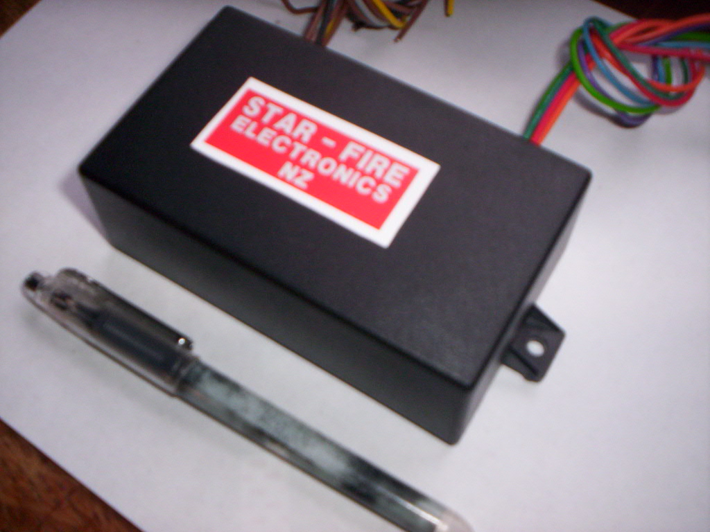
This STARFIRE CDI is a universal unit designed to replace ALL models KH400/ H1D /H2 series of Kawasaki triples. The unit measures 110x65x40mm with mounting lugs 12mm between centers. Units are built using high quality branded components, not Asian generics, mounted on quality fibreglass printed circuit boards. The internal circuitry is a direct copy of the original Kawasaki fitted units, using upgraded and modern components. This model does have extra support to cover a selection of models and years.
------------INSTALLATION INSTRUCTIONS FOR KH400------------
1) Mount unit to bike using existing mounting platform or custom bracket. The
distance between mounting holes is 12mm.
2) Connect the BLUE wire from the CDI to the BLUE wire in the harness (ignition
coil center)
3) Connect the RED wire from the CDI to the ORANGE wire in the harness (ignition
coil left)
4) Connect the GREEN wire from the CDI to the GREEN wire in the harness
(ignition coil right)
NOTE The above coil wires are accessed via the 3 two terminal plugs and sockets.
All 3 BLACK wires from the ignition coils must be returned to ground, only the
three coloured wires connect to the CDI. The reason for this slight
inconvenience is to REDUCE the connections required to the replacement CDI.
5) Connect the YELLOW wire from thje CDI to the WHITE wire in harness (magneto)
6) Connect the ORANGE wire from the CDI to the RED/WHITE wire in the harness.
(pulse coil left)
7) Connect the LIGHT GREEN wire from the CDI to the GREEN/WHITE wire in the
harness. (pulse coil right)
8) Connect the PURPLE wire from the CDI to the BLUE/WHITE wire in the harness.
(pulse coil center)
9) Connect the GREY wire from the CDI to the BLACK/WHITE wire in the harness.
(ignition switch)
10) Connect the BROWN wire from the CDI, either one, to the RED wire in the
harness. (high voltage coil)
NOTE All the above except 9 are accessed via the SIX PIN CONNECTOR. Again,
the BLACK wire must be grounded.
11) Connect the BLACK wire from the CDI to a firm ground.
12) cut short the 1 unused brown wire from the cdi.... not required for this
model.
------------------------------------------------------------------------------------
--------- INSTALLATION INSTRUCTIONS H1D/H2 (replaces all 4 units with ONE
box!)---------
Mount unit to bike using existing mounting platform or custom bracket. The
distance between mounting holes is 12mm.
1) Identify the left/center and right RED ignition coil wires, they are all
RED.
2) Connect the BLUE wire from the CDI to the RED wire in the in harness.
(ignition coil center)
3) Connect the RED wire from the CDI to the RED wire in the harness. (ignition
coil left)
4) Connect the GREEN wire from the CDI to the RED wire in the harness.
(ignition coil right)
5) Connect the GREY wire from the CDI to the BLACK/WHITE wire in the harness.
(ignition switch)
6) Identify the three WHITE wires from the pulse coils.
7) Connect LEFT pulse coil to CDI ORANGE wire.
8) Connect CENTER pulse coil to CDI PURPLE wire.
9) Connect CDI RIGHT pulse coil to CDI LIGHT GREEN wire.
10) Connect the BROWN wire #1 from the CDI to the GREEN wire in the harness.
(magneto high speed winding)
11) Connect the BROWN wire #2 from the CDI to the WHITE wire in the harness.
(magneto low speed winding)
12) Connect the BLACK lead from the CDI to the BLUE lead in the harness, and
GROUND BOTH to the frame.
13) Cut short the unused YELLOW wire from the CDI unit, it is not used with
this model.